 FLSmidth, a leading supplier of mine and terminal stockpile equipment, says the industrys current focus is
mainly
on efficient operation including improving the accuracy of inventory information and integrated
processes that
range from order handling to shipment reports.
Continuity of material flow across a mine
site is essential for profitable production,
and the many inputs that affect how blasted
rock, crushed ore, concentrates and waste
can be efficiently moved from one point to
another range from macro factors terrain,
climate or geology, for example to
microscale properties such as moisture
content, friability and crushed particle size,
in addition to the overall suitability of the
sites bulk material handling equipment.
Many of these items can vary by region
and even across a specific site as weather,
active mining areas or ore characteristics
change throughout a mines life. Combine
them with the extensive range of bulk
material-handling equipment currently
available on the market, and what emerges
is often a quandary for mine operators:
how to configure an optimal material flow
scheme, or unwittingly waste time and
money on an underperforming system.
Like almost any phase of modern mining,
the handling of bulk mined and processed
material is a steadily evolving blend
of brute force and digital strategy. Data
now plays a much bigger role in how companies
identify, acquire and operate the
systems needed for efficient material handling.
In the past, the only item of interest
to a producer in a cubic yard of ore was
its mineral content; but in an increasingly
expanding digital environment, each cubic
yard can be associated with an electronic
data packet pertaining to origin, grade
and energy consumption needed to move it
along the mining chain, and other information
of use to the producer for controlling
energy costs, analyzing machine efficiency
and streamlining downstream logistics.
Its a trend driven by a need to stay
competitive in a commodities market
that can be unforgiving to producers that
dont maintain tight control over their
mine-to-port delivery efficiency. Stockpile
management is one of the most obvious
areas of industry attention, with the high
volume of tonnage, equipment size and
constant movement of material in and out
offering a fertile field for innovations in
data analysis and automation, but as well
see later in the article, some of the less
costly and visible components commonly
used in material transport systems, such
as chutes and hoppers, also warrant more
awareness of design and maintenance to
preserve smooth material flow.
Taking Stock
As global mineral production rates increase
to meet market demand, so does
the need for closer focus on stock control
issues such as optimum stockpile size,
stockpile turnover period, stock level fluctuation
and timely stock management.
E&MJ asked Franz Rietschel, global product
line manager, autonomous material
handling, at FLSMidth to comment on
recent trends in stockpile management.
E&MJ: Against the backdrop of a global
business environment in which prices,
shipping costs, labor availability and market
demand can exhibit strong volatility, is
the role of stockpiles as a buffer between
a mine and its delivery-logistics structure
drawing more attention from producers?
Rietschel: Yes, stockyards still have their
clear role as a buffer for the next consecutive
step, but we do not currently see
that customers are expanding their footprint
to increase this buffer. The focus is
mainly on efficient operation, reducing
inaccuracies in inventory information and
integrated processes that range from order
handling to shipment reports.
Less human interaction can speed
up processes and reduce the risk of mistakes.
In addition to more efficient operation,
a fully integrated system can take
more constraints into account, such as
material or energy prices, shipping cost,
demurrage prioritization or other factors,
to enable computer-based decision making
toward autonomous material handling.
We have noted several brownfield projects
where existing infrastructure is getting
replaced because existing machines are reaching the end of their lifetime,
capacity is too insufficient or refurbishments
are not efficient.
E&MJ: What influence, if any, does inthe-
ground ore-grade variability, decreasing
mill head grades and similar adverse
factors have in stockpile functions such
as blending operations, quality control,
etc.? How can your companys offerings
help in these areas?
Rietschel: Material reconciliation from a
geological model to real handled quality
is still a challenge as input for production
planning, but the gap can be closed by
increased availability of data. More accurate
blending is possible thanks to the
recently developed capability to model
a digital twin of belt conveyor systems.
Based on the model, feed rates can be
controlled to maintain a certain ratio.
Digital solutions like LoadIQ offer more
qualified information about the input and
output sides, which can be used for further
improvement. LoadIQ is a smart load
optimization tool that enables miners to
increase throughput by 3%-6% and reduce
energy consumption. This is done by
utilizing a system of smart sensors and AI
software to automatically determine the
optimal load for all milling conditions.
Elsewhere, we also have the ECS/ProcessExpert
system that stabilizes the key
processes, manages and corrects process
disruptions and is a mill load target optimizer
automatically adjusting the mill
load according to weight target and process
conditions.
For grade tracking and 3D stockyard
visualization, FLSmidth has BulkExpert
Stockview, which tracks the material distribution
based on process signals of the
machines (e.g., travel position, slew and
luff angle). Quality management in the
stockpiles is possible thanks to calculated
models. At any time, such digital twin of
the pile provides an operator inventory information
even of the inside of the pile.
For ore where different grades have
different prices, the separation and tracking
of this material in the stockyard is
essential and customers are increasingly
requesting this functionality.
E&MJ: In what ways are digital technologies
helping improve stockpile operations,
monitoring and strategies?
Rietschel: Digital solutions can add value
where the optimization of physical assets
ends. Integration is the key for bigger
process improvements. An ongoing installation
at two export terminals is a good
example of where a digital twin of a belt
conveyor system will help to avoid overloading
the belt conveyor system. Modelling
the material allows feeding-source
machines to collaborate with each other,
not only to flatten peaks but also to compensate
for each other to boost production
while reducing the risk of overload.
Priority on Project
Preparation
Across the industry, mine project owners
are reporting that upward trending cost
curves for energy, consumables and other
items are taking larger than expected
bites out of their contingency funds, and
many companies are scrambling to keep
projects moving along on schedule in the
face of material shortages, shipping delays
and labor scarcity.
 Pointing out the overall importance that proper design and integration of material transfer points
and chutes have
on plant performance, Weba Chutes recommends early involvement of an EPCM
firm in bulk material handling
projects to optimize planning and placement of these components.
For example, the most recent release
of the IHS Markit PEG Engineering and
Construction Cost Index (ECCI), a service
that tracks industry trends that
can affect wage and material inflationary
movements in the construction and
engineering industry, shows that both
shipping and construction costs have
skyrocketed in the North American market,
while other reports indicate the
global mining industry is grappling with
inflationary increases in the 4-7% range,
with the costs of certain consumables
such as fuel rising at a much higher
rate. The ECCI index score increased
from 75.3 in February 2022 to 85.5 in
March, the highest figure for the indexs
10-year history. Its subcontractor labor
index rose 4.8 index points in March to
79.3 from 74.5 in February, while the
sub-index for materials and equipment
costs rose 12.6 index points to 88.2.
In a business climate like this, preplanning,
good design and proper maintenance
can protect material handling
projects and existing system performance
from being knocked off kilter. And, some
of the industrys leading material handling
system providers would like to remind
producers that attention to these
details can yield significant benefits even
in areas that typically dont get a high
level of engineering scrutiny transfer
points, chutes and hoppers, for instance.
South Africa-based Weba Chute Systems
noted in a recent blog post that
there is growing recognition that transfer
points and chutes have a significant impact
on overall plant performance. The
mining sector relies increasingly on Engineering,
Procurement and Construction
Management (EPCM) firms for new builds
and expansions, allowing miners to focus
on their core mandates.
The advantage of using EPCMs is their
design and execution capability, which
many mining companies have elected
to reduce over the years. According to
Weba Chute Systems Project Manager Ted Cruikshank, this usually streamlines
the input of suppliers, allowing a focused
and efficient relationship. Working closely
with an experienced transfer point OEM
at an early stage of a project will ensure
chutes are optimally planned upfront.
For EPCMs to get the best value from
our decades of experience in transfer
points, they really need to talk to us early
in the project cycle ideally at bankable
feasibility stage, Cruikshank said. This
can ensure that transfer points are optimally
planned upfront, as the positioning
of this infrastructure is vital to many other
aspects of the plant.
He noted that in the past five years
or so, there has been a growing recognition
that transfer points and chutes
have a significant impact on the overall
performance of process plants. They were
previously considered as relatively small
additions to plant layout, with more attention
being paid to the larger items, which
carried a higher capital value.
What is now being appreciated is
that poorly positioned or inadequately designed
chutes can disrupt the entire plant
process, costing mines dearly in terms of
downtime, maintenance and repairs, he
explained. Mines pay the price of substandard
equipment by having to deal
with choking in the chutes, high wearand-
tear, spillage, skew belt loading,
damaged idlers and other problems.
These challenges can be avoided if EPCMs
engage transfer point specialists early
on, so that these experts help inform the
plant layout before final design decisions
need to be taken. By getting the right input
in good time, EPCMs can also quote
more accurately on their project costs.
For instance, if the positions and
heights of key equipment in a plant have
already been decided before we get involved,
it means that designs must be
altered in order to achieve optimal results,
Cruikshank said. Alterations to
existing plans invariably means added
costs, which the end-customer is never
happy about. By arriving at the right
design first time around, the costing is
more predictable and the reputation of
the EPCM is enhanced.
Cruikshank said the height of a transfer
point is an important variable in properly
controlling the flow of ore through chutes
and on to receiving conveyors with optimal
belt loading, low impact and reduced
wear. Before design stage, Weba Chute
Systems gathers detailed technical information
from the client on the mines material
characteristics, lump sizes, tonnages,
particle size distribution and other factors.
Transfer chutes can then be custom-engineered
to the right configuration, matched
to the ore that needs to be moved.
We regularly see situations on mines
where this process has not been followed,
and where chutes are still regarded just
as simple platework, he said. At one
manganese mine in the Northern Cape,
management called for our assistance
when material flow across the operation
became disrupted by dysfunctional
chutes that would not last.
Weba Chute Systems involvement led
to replacement of almost 30 chutes on a
single site so that mine operations could
return to normality, Cruikshank noted.
Designing Chutes for
Max Performance
Weir Minerals said it views chutes as
the unsung heroes of comminution
flowsheets. When E&MJ asked why, the
company offered to have its experts explain.
Heres what Jon Waite, engineering
manager, pumps, PCD & comminution;
Fernando Domingo, senior engineer; and
Nirmal Weerasekara, principal engineer
all based at Weirs Artarmon, New
South Wales, Australia operations said:
OEMs know, broadly speaking, how their
feeders, crushers and screens will operate.
They perform consistently, which means
process engineers know what to expect
from them when developing flowsheets.
Understanding how the material will behave
at the transfer points, on the other hand, is
highly variable and, therefore, more diffi-
cult to predict. Optimal chute design will
have a profound impact on the way equipment
operates downstream which will, in
turn, affect overall plant performance.
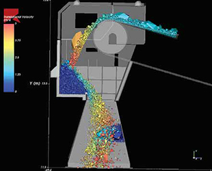 Weir Minerals uses Discrete Element Modelling (DEM) software, which
simulates particle flow, to understand the
intricacies of particle-particle,
particle-structure and particle-machine interactions, as well as to visualize
how
particles will flow through the chutes its designing.
When designing chutes for specific
applications and plants, the Weir Minerals
team spends a lot of time working
through how to control the material
flow, while minimizing dust, spillage and
blockage, among other things.
For screening applications, its important
to consider how fast the material will
enter the screen and how it will disperse
across the screen in order to achieve the
best screening performance. Ideally, the
material needs to be evenly spread across
the screen to promote greater stratification
of the feed material, allowing more
finer particles to work through the material
bed, leaving a higher concentration of
coarse and large particles to rise to the
top. Needless to say, stratification has a
major influence on plant screening process, screening efficiency and the quality
of product. Similarly, in crushing applications,
uneven feed can adversely affect
crushing performance and efficiency and
result in lower quality product.
The speed and trajectory are also important
considerations because if the material
is flowing too quickly and in a less than
ideal path, then any oversized particles can
cause premature damage to immediate
contact surfaces, like feeder pans, screen
panels and chute linings of the discharge
chute. Furthermore, if the particle distribution,
speed and trajectory of the material
isnt properly accounted for it can lead to
blockages at the transfer points. A discharge
chute, for instance, typically feeds
on to a receiving conveyor, so the material
needs to exit the chute at a speed that is
proportional to the speed of the conveyor.
Importantly, the Weir Minerals team
looks at the overall system, not just each
individual chute. In other words, successful
chute design only works if the
engineers take a system-wide approach.
Primary, secondary or tertiary crushing
circuits have specific chute design requirements
to accommodate the different
material and flow properties leading to
each chute. Thus, its essential that the
process engineers understand the plant
process flow, target throughput and the
customers product quality requirements.
One of the advantages Weir Minerals
claims over its competitors is that, as an
OEM, it has a full range of comminution
equipment that it designs and manufactures
and, therefore, knows intimately how
it operates. Additionally, this equipment is
fully supported by a team with a broad skillset
and diverse experience, made up of process
engineers, design engineers, product
experts and data scientists, among others.
Weir Minerals treats each chute as a
customized design. These are fully welded
pieces of equipment, which means
theyre non-adjustable once on site. Its
imperative, therefore, that the team is
meticulous at every stage of the planning
and design process.
Simulation
Weir Minerals uses Discrete Element
Modelling (DEM) software, which simulates
particle flow, to understand the intricacies
of particle-particle, particle-structure
and particle-machine interactions, as
well as to visualise how particles will flow
through the chutes its designing. These
simulations help the engineers understand
the transitional flow of the material,
where the highest bulk pressure in the
chutes may lead to potential high wear
areas and where potential blockages may
occur. The goal is to minimize particle
size segregation on conveyers and ensure
even size distribution of particles across
the cross-section to achieve optimum
feed, for example into a crusher.
In brownfield process optimization projects,
reliable plant process data is vital
as theres a direct correlation between the
quality of the data input into the simulation
and the accuracy of the modelling that informs
and guides the process optimization.
In greenfield projects, there may be
instances whereby accurate data is diffi-
cult to come by. In such cases, the Weir
Minerals team draws on their experience
and knowledge to make predictions based
on how a particular ore typically behaves.
Spodumene behaves very differently to an
iron ore, for example, and that needs to
be taken into account.
There are many principles involved
with how rocks fall and theres always
variance depending on the size and shape
of the rocks. Some rock characteristics
and processes generate thin, slabby material,
which falls differently to a rounded
material, which typically rolls or tumbles.
The team also weighs up the PSD and
calculates how that will affect the way the
material behaves. This is guided and informed
by plant data, simulations, as well
as the expertise and experience of Weir
Minerals multidisciplinary team.
 A suppliers knowledge base gained from prior-project experience can help
mines predict how specific types of ore,
for example, will behave in order to
avoid material-flow operational problems.
Fault scenarios are also simulated to
pre-empt potential problems that could
lead to the shutdown of production or
catastrophic failure. The team can model
situations where theres a blockage
in the stream, which, in turn, can lead
to material building up in the discharge
chute. Its important that operators have
the confidence that, when the conveyor
is restarted, they are going to be able to
clear the chute. Simulated fault scenarios
such as this forestall problems before its
too late thats to say, before the chute
is designed, manufactured and installed.
Chutes are often overlooked in comminution
flowsheets. But, in many respects,
they embody a trend in the mining industry
toward the utilization of data and
simulation to drive insights and optimize
equipment and processes.
Weir Minerals engineers are proficient
in the realm of data once the sole domain
of data scientists and understand
its potential; thus, it increasingly forms an essential element of how they work often
seeing and interpreting data differently
and unlocking previously hidden value.
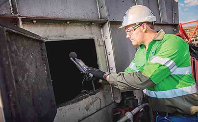
Flow Aids for Avoiding Clogs
Brad Pronschinske, global air cannon
product manager at Martin Engineering,
described the drumming sound of bulk
material hitting the metal sides of a hopper,
bin or chute during loading as the
sweet sound of production. If the noise
becomes muffled, he explained, it likely
indicated that the vessel is filling up, or
it could signal the presence of buildup on
the inside walls or discharge gate. There
are a number of design and maintenance
options available to reduce or prevent
buildup problems, however.
Once coarse material adheres, the
buildup is generally fast and dense, eventually
resulting in downtime to remove.
When operators notice reduced material
flow, spillage or accumulation on conveyors,
they know a clog has formed. Seeking
ways to address it quickly without the
proper tools or training can also be the
moment when workplace safety degrades.
Flow aids are engineered to safely
clear and prevent clogging, promote material
flow and avoid costly downtime. To
know what technology will work best for
a specific application, the first step is
understanding how, where when and why
clogs happen in any given vessel or transfer
point. The second step is removing
any worker involvement in clearing the
clog, aside from pushing a button to activate
the flow aid if it isnt automated or
controlled by logistical software.
Clogging, Loads and Carry Weight
Although hoppers are designed to be filled
with a specific volume of material, they
generally exist to consolidate and direct
the flow. Although they are not storage
vessels, an awareness of the maximum
load is important. Some operators match
the hopper size to transport bin size (for
trains, trucks, etc.), repeatedly filling and
emptying them. This makes load requirements
especially important in those cases,
since capacity is reached dozens or
hundreds of times per day under many
conditions. When working with bulk solids,
environments with high moisture and
freezing often experience clogging. Wide
variations in the size and shape of material
can also affect the flow characteristics,
leading to buildup and clogs.
If a hopper is not designed to carry the
material load at full capacity, then a sudden
surge of material or a clog can lead
to danger. Even if a vessel is engineered
properly, abrasion from loading can cause
the walls of the hopper or chute to wear
thin over time, decreasing their ability
to carry the weight, potentially causing
them to buckle and possibly injure anyone
working near the structure.
Structural standards determine the
proper design of the equipment to handle
the load. Loads are categorized as:
Dead load The total weight of the
structure, including attached items and
equipment supported by the structure.
Live load Forces exerted from stored
material, including high and low pressures
caused by flow. Essentially, that
includes anything independent of the
structure, including snow, positive and
negative air pressure, wind or seismic
load and forces from materials stored
against the outside.
Thermal Load Caused by temperature
differences between the inside and outside
faces of the wall.
Settling Load Force from uneven settling
of the structure.
Weather, weight/size of the material,
structural design and load distribution are
all factors that can lead to clogging and/or
an overcapacity situation. The weight of
the material can contribute significantly
to structural integrity and load distribution,
as well as the force of the material
once it is discharged. The discharge surge
can overwhelm the bin or conveyor onto
which the material is flowing, so understanding
the weight of the material in the
clog is important.
Once the clog has been detected, the
weight of the clogging can be calculated
using a load that is equivalent to the capacity
of the chute or vessel in question,
with due reference to the slope angle.
The material normally within the chute or
vessel may be deducted. The actual bulk
weight must be taken for the calculation.
Discharge Point Geometries
Discharge channels come in varying
shapes, depending on the vessel and the
material flow characteristics. Spouts that
are narrow, such as those found on conical
or pyramidal shapes, direct flow in
a vertical column either into a chute or
specific loading area. Slotted spouts, like
those found on the wedge or transition
shapes, distribute material in a narrowly
defined line for loading onto conveyors or
into containers (trains, trucks, etc.)
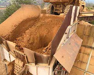
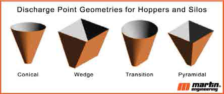 Mine operators choose discharge point shapes based on a series of load and flow factors. The wrong shape
selection
can lead to clogging and excessive, possibly unsafe maintenance activity.
The geometry of a vessel must match
that of the discharge point, or it will be
prone to clogging. Mine operators carefully
choose discharge point shapes based on
a series of load and flow factors. The slope
angles in discharge point geometries can
contribute to clogging based on material
characteristics, the specifications of the
application or the placement of the vessel.
These discharge points can feature
gates or grates that stop or separate the
material. Gates halt material flow for incremental
filling of transport bins on a
train or truck. Grates can be used to slow
or direct the flow of material when loading
onto a conveyor. Either way, operators find
that these components can exacerbate
clogging by stopping or slowing material
at a structural choke point of the vessel.
Unsafe Practices
Once a clog has been detected, there are
several unsafe practices that at the time
may seem harmless, but frequently cause
serious worker injuries or fatalities year
after year. The two main causes of injury are sudden discharge of adhered material
and entrapment.
One unsafe method is beating the vessel
walls with mallets or other objects to
loosen adhered material. Over time, the
more the walls are pounded, the worse
the situation becomes, as the bumps and
ridges left in the wall from the hammer
strikes will form ledges that provide a
place for additional material accumulations
to start.
Another hazardous practice is poking
or lancing underneath the clog at the discharge
point. This can result in a sudden
surge of falling material, burying or crushing
the worker(s) below.
Perhaps the most prevalent cause of
worker injuries and fatalities is confined
space entry of the vessel. Workers can
potentially sink into the material in the
center, or the load could be bridging and
suddenly release. If a worker enters the
vessel and stands on a bridge, a sudden
discharge could pull the worker into the
cavity. Another serious hazard of confined
space entry is material buildup on the
sides of the vessel, reaching higher than
the worker. This buildup could fall from
above, causing serious injury or burial.
Air lancing the clog from the mouth
of the vessel at the top is an option many
operations have chosen, but guardrails are
highly recommended. The reach of the
lance and the pressurized air stream must
match the size of the vessel. Workers can
fall in trying to reach the lance down to the
clog, even if guardrails are present.
All these hazards can be avoided by
introducing flow aids to the vessel to mitigate
clogs, promote material flow and reduce
downtime. As the term implies, flow
aids are components or systems installed
to promote the transport of materials
through a chute or vessel, controlling dust
and spillage. Flow aids come in a variety of
forms, including rotary and linear vibrators,
high- and low-pressure air cannons and
aeration devices, as well as low-friction linings
and special chute designs, to promote
the efficient flow of bulk materials.
These modular systems can be combined
in any number of ways to complement
one another and improve performance.
The components can be used
for virtually any bulk material or environment,
including hazardous duty and extreme
temperatures. One of their primary
advantages is that an operation can obtain
a level of control over the material
flow that is not possible any other way.
When employing flow aids, its critical
that the chute and support components
are sound and the flow aid is properly
sized and mounted, because the operation
of these devices can create potentially
damaging stress on the structure. A
properly designed and maintained vessel
will not be damaged by the addition of
correctly sized and mounted flow aids.
Its also important that any flow aid
device be used only when discharges are
open, and material can flow as intended.
The best practice is to use flow aids as
a preventive solution to be controlled by
timers or sensors to avoid material buildup,
rather than waiting until material accumulates
and restricts the flow. Using
flow aid devices in a preventive mode improves
safety and saves energy, since flow
aids can be programmed to run only as
needed to control buildup and clogging.
Engineered Vibration
The age-old solution for breaking loose
blockages and removing accumulations
from chutes and storage vessels was to
pound the outside of the walls with a hammer or other heavy object. A better solution
is the use of engineered vibration, which
supplies energy precisely where needed to
reduce friction and break up a bulk material
to keep it moving to the discharge
opening, without damaging the chute or
vessel. The technology is often found on
conveyor loading and discharge chutes but
can also be applied to other process and
storage vessels, including silos, bins, hoppers,
railroad cars, screens and feeders.
Some mining operations and methods
can result in wet and tacky material.
There is another innovative solution
that prevents carryback from sticking to
the rear slope of a discharge chute. The
dribble chute uses material disruption to
reduce friction and cause tacky sludge
and fines to slide down the chute wall
and back into the main discharge flow.
By addressing these issues, operators can
reduce maintenance hours, equipment
replacement and downtime.
Air Cannons
One solution for managing material accumulation
in chutes and vessels is the
low-pressure air cannon, pioneered and
patented by Martin Engineering in the
1970s. It uses a plants compressed air
to deliver a powerful discharge to dislodge
the buildup. Cannons can be mounted on
metallic, concrete or wood surfaces. The
basic components include an air reservoir,
fast-acting valve with a trigger mechanism
and a nozzle to distribute the air in
the desired pattern to clear the accumulation
most effectively.
The device performs work when compressed
air (or some other inert gas) in
the tank is suddenly released by the valve
and directed through an engineered nozzle,
which is strategically positioned in
the chute, hopper, duct or other location.
Often installed in a series and precisely
sequenced for maximum effect, the network
can be timed to best suit individual
process conditions or material characteristics.
The air blasts help break down
material accumulations and clear blocked
pathways, allowing solids and/or gases to
resume normal flow. In order to customize
the air cannon installation to the service
environment, specific air blast characteristics
can be achieved by manipulating
the operating pressure, tank volume,
valve design and nozzle shape.
Nozzle and cannon designs have come a
long way since their introduction. Air tanks
were directly connected to nozzles, which
used to be open pipes that shot across the
stream or shaped and welded to the walls
to direct the air shot toward the clog-prone
area. In a punishing environment like mining,
operators found these nozzle designs
would wear quickly, requiring replacement
and downtime. Open pipes often suffered
from blockage that became too dense for
the cannon to clear, requiring removal of
the tank. Directional nozzles would get
crushed or also become blocked, requiring
confined space entry and hot work to
remove and replace. To mitigate the stoppages
and extra labor, a Y-pipe assembly
can be permanently mounted to hold the
tank and nozzle, which can be changed in
minutes from outside the vessel. Many designers
now proactively include the mountings
in new designs so that a future retrofit
can be done without hot work permits or
extended downtime.
Valve Replacement
Over time, the valve in an air cannon will
wear, even under normal conditions, and
it is common practice to refurbish them
rather than replace them with new ones.
Because clearances and fits are critical to
proper operation, its recommended that
flow aid devices be rebuilt and repaired by the manufacturer, or that the manufacturer
specifically train plant maintenance personnel
to properly refurbish the equipment.
To simplify the process and avoid system
downtime, one manufacturer has created
a program to supply factory-rebuilt air
cannon valves that carry the same warranty
as new valves. Customers can receive
a standard pallet-sized container with six
refurbished valves, so theres no need for
users to rebuild worn-out components. The
changeout can be accomplished in just ten
minutes, at less than half the cost of new
valves. The used valves are shipped back
to the company, where the units are rebuilt
to as-new condition by factory-trained
technicians. Customers save time and
money, with no need to stock repair parts
or provide the training / labor to rebuild.
Case Study Mexico Coal Mine
A coal mine in northern Mexico was experiencing
problems with material clogging a
high-volume discharge chute leading from
a main raw material conveyor. Handling
12,000 metric tonnes (13,227 tons) of
coal in the plants 24-hour operation cycle,
tacky dust and aggregate would cling
to the sides of the transfer point and clog
it 2 to 3 times per day. Two people would
manually dig out the clog and sometimes
enter the chute, causing an interruption
in operations for up to 6 hours every day.
Cleaning and maintenance caused a potential
workplace hazard, reduced productivity
and raised the cost of operation.
Operators invited technicians from Martin
Engineering to offer a solution. They
installed two 35 liter (9.25 gallon) Martin
Hurricane air cannons. Connected to the
plants existing compressed air system, the
cannons use positive-acting valves that fire
a powerful shot of pressurized air into the
chamber along the material path to promote
constant flow and dislodge adhered
material. Offering more force output than
designs double their size with considerably
less air consumption, the compact tanks
measure only 16 in. (406 mm) in circumference,
24.92 in. (633 mm) long, and
weigh 78 lb (35 kg). The units fire a shot
of air at up to 120 PSI (8.27 bar).
Designed with safety and low maintenance
in mind, the cannons feature a
centrally located outward-facing valve assembly
that can be replaced within minutes,
without the need to remove the tank
from the vessel. To prevent the risk of unintentional
firing due to drops in pressure,
the positive-firing valve requires a positive
signal from the solenoid in the form of an
air pulse to trigger release.
After 8 months of operation, operators
reported the air cannon system decreased
unscheduled downtime significantly. Labor
for cleaning was drastically reduced,
with no reported need for chute entry.
We are very satisfied with this solution,
a manager said. Company officials are
working with Martin Engineering to examine
other sections of their process at the
facility and devise similar solutions.
Let The Material Flow
Over time, all components wear or break
under normal operating conditions. Most
of these devices can be rebuilt to extend
their useful life. Managers will agree that
it is more economical to fix or replace a
single component than an entire chute or
hopper system prematurely. In addition to
the positive economic outcomes are safety
outcomes. Less maintenance and exposure
to dangerous practices means fewer
chances for injury. When taken together,
modern flow aids improve production, efficiency, and lower the cost of operation.
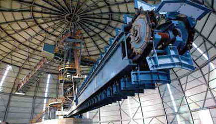
Hägglunds Introduced Fusion at SME 2022
By Steve Fiscor, Editor-in-Chief
One of the highlights from the 2022 Society of Mining, Metallurgy
and Exploration (SME) conference was the Hägglunds
Fusion drive system. As the new definition of compact power,
Fusion houses the motor, pump, cooling system and controls in
one package, allowing for a smaller footprint.
 The Fusion drive systems house all components in one package.
For the first time, miners working with materials handling
systems have a plug-and-play answer to drive system needs. The
Fusion drive system puts everything on the torque arm, from the
hydraulic motor and pumps to the cabinet that houses them.
That makes high torque and total reliability available from a
single unit in a footprint that was previously unthinkable,
according to Hägglunds.
This system eliminates the gearbox and the associated foundations
and alignment issues.
These systems would mount directly on a machine shaft for a
small conveyor or an apron feeder anything with a lower power,
high-torque requirement, said Brian Howell, manager sales and
operations for Hägglunds Products & Solutions. The mine attaches
a 460-volt, 3-phase power source and its ready to run up to 60
hp. Its ideal for retrofit applications. Several mines are considering
Fusion drives to replace older mechanical drive systems.
Hägglunds also displayed the Atom motor. Possessing far more
power than motors of similar size, the Atom is a tiny, power-dense
package. With output of 500 hp at 400 rpm, this will be a real
game changer for mines with space limitations, Howell said.
The Atom has a maximum torque of up to 13.6 kNm and a specific torque of 40 Nm/bar. Because it supplies full torque at speeds
up to 400 rpm, it has a maximum power of 394 kW (528 hp) that
outstrips other motors in its class, according to Hägglunds.
In the past, mining companies may have taken a pass on
the use of Hägglunds motors for drive systems because of their
bulky nature, but the Atom will make them reconsider that decision,
Howell said. Hägglunds strengths, such as maximum
torque from zero speed and built-in protection from torque
The Fusion drive systems house all components in one package. peaks, are now included in small, easy to install packages.
As featured in Womp 2022 Vol 04 - www.womp-int.com