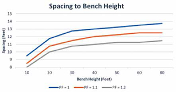
Figure 1Spacing to bench height for various powder factors (example is with a 4-in.
borehole).
Powder Factor: The Ineffective
Design Tool
More modern approaches to spacing and blast design dramatically improve
performance of blasts
By Anthony Konya, M.S., and Cal Konya, Ph.D.
During the first few centuries of blasting the thought process was that each rock, depending on type and structural geology, had a specific powder factor that when achieved would give optimal fragmentation. After equations were developed to determine burdens, the blaster could then isolate the powder factor as the key performance indicator and adjust the spacing to achieve the proper value.
This design approach allowed many blasters to begin to standardize specific patterns to achieve approximately the right powder factor. This is where patterns such as equilateral triangle patterns originated, giving the blaster an easy method to lay out a blast with minimal calculations. Under this design approach a blaster would not have a definite spacing and the powder factor would slightly vary with bench height.
This also led to the belief that benches that were two to three times the burden would be the lowest cost benches; this has since been disproved. As the bench height increased, and the spacing was held constant, the powder factor would increase along with the bench height.
During this time blasters could not understand why this powder factor approach worked in some situations, but in others it failed miserably. Geology must be to blame and that site was just different was the common excuse. In Europe in the 1970s, Kuznetsov, a Russian mining engineer, completed his powder factor studies. Kuznetsov received grants from the government to study the ideal powder factor for all rock types to achieve the best fragmentation. His studies lasted for nearly a decade and, at the end of his studies, he determined that no ideal powder factor exists, and many variables go into a blast to determine the fragmentation and the other outcomes of a blast. This was known in the USA well before the 1970s.
The Physics of Spacing
In the early days of blast design it was
believed that a blast broke in an equal
radius around a borehole and that depending
on the powder factor of a blast
the fragmentation and throw of a blast
could be changed. This thought process
led to the modification of spacing to
achieve increased powder factors, and in
many situations led to blasters having a
smaller spacing than burden. As research
increased it was discovered that spacing
was an extremely important variable in
blast design, and Richard Ash was quoted
in 1963 saying, It can be generally assumed
that uniformity in sizing is a direct
result of the spacing. If on firing a single
hole the rock is satisfactorily broken and
cleanly removed without excessive displacement,
it may be assumed the burden
is satisfactory. Too often then blasters reduce
the burden rather than extend the
spacing in their desire to eliminate boulders
or to make rock sizing more uniform.
Since the 1960s it has been discovered
that spacing is a critical variable
that relies on a 4-D design approach
which includes the physical constants of
a blast and the timing of the blast. The
spacing will also affect, to a large degree,
the uniformity of the fragmentation, the
fragmentation sizing, and the throw of the
material from a blast.
The spacing of a blast is determined by the burden, the bench height, and the hole-to-hole timing of a blast. Should the spacing be too small for the timing of the blast, the boreholes will not break into the burden to a major effect. They will instead interact with each other to a large degree, producing fines between boreholes and boulders in the burden of the blast. Should the spacing be too large for the timing of the blast, the boreholes will not interact with each other in the burden and instead large boulders will be produced between boreholes. In both of these situations backbreak will occur and a sawtooth effect will be visible on the subsequent face.
Two old school design approaches exist, one which is directly based on powder factor and the second which has its origins in powder factor. Both of these methods are still widely used today; it will be discussed as to why they are inappropriate and are leading mines to a large increase in unneeded operational expenses. The first that will be discussed is the traditional powder factor design approach.
A good blaster may look at the results of a blast and say, well that material is too coarse and numerous boulders are in the burden of the muck pile perhaps a higher powder factor is needed. The blaster may then decide on a powder factor of 1.1 lb/ yd3 and this would reduce the spacing from about 13 ft to approximately 12 ft. The next blast is fired; the material is still coarse and boulders are still prevalent. The blaster then reduces the spacing to 11 ft to achieve a powder factor of 1.2 lb/yd3; the rock is still coarse and somehow more boulders exist than before. It is then assumed that the problem is not in the blasting, but in the geology and good fragmentation cannot be achieved. The actual problem, however, was that the 13 ft spacing was already too small and further reductions increased the problem. The problem was the approach to the blast design.
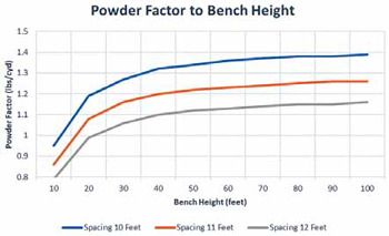
The second old approach to blast design was also based on powder factor. Specific patterns were created to achieve powder factors for certain scenarios. This would be a pattern such as the equilateral triangle pattern, where the blaster would lay out blastholes with a set burden in an equilateral triangle shape, giving a spacing of about 1.15 times the burden. This approach sets the spacing at a specific number and the powder factor slightly varies based on the bench height. Under this design approach the powder factor has a direct relationship with the bench height.
The way this design is used in practice today is that a blaster will set the spacing to some number that they are familiar with for that explosive diameter. In Figure 2, three different spacings are shown. In this case the powder factor is variable. Most blasters understand that firing a bench with a height that is less than 2.5 times the burden will produce poor results. This design approach then leads blasters to believe that the most economical blasts are those where the bench height is near that 2.5 times the burden, because that is the lowest powder factor on the graph. This design approach leads to large increases in cost to mines because the actual effects and mechanics behind a blast are not fully understood and in turn performance is poor.
Modern Spacing Methods
Modern spacing of boreholes is not based
on setting a powder factor or using a preselected
design that only works in unique
situations. Instead the spacing of blastholes
should be selected based on the desired
outcomes of the blast. The spacing
will then be designed in accordance with
the bench height, burden, and the holeto-
hole timing. For the rest of this article,
it will be assumed that the boreholes
along a row are not fired instantaneously
along a row. In this case, one can simplify
the spacing design further to where we assume
that the spacing will scale with the
burden. In this case, the spacing ratio will
be defined as the spacing between boreholes
divided by the burden of a borehole.
This spacing ratio will then be changed
based on the stiffness ratio of the blast,
where the stiffness ratio is defined as the
bench height divided by the burden.
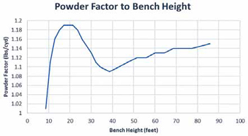
When the stiffness ratio of the blast is less than 4, the bench will be considered a low bench. The lower the stiffness ratio of a blast, the worse the blast will function. For stiffness ratios near 1, the bench will break with a cratering mechanism. This same effect will also cause the spacing ratio of the blast to be reduced and, when the bench height is equal to the burden, the spacing ratio will also equal 1. As the stiffness ratio then increases, the spacing ratio will also increase. Assuming that the increase in stiffness ratio is from an increase in bench height, the powder factor variations are shown in Figure 3.
The graph presented in Figure 3 may appear strange at first as the powder factor dramatically increases, then quickly falls, and then again slowly rises. This will be explained further and why this phenomena occurs, but it may be easier to understand by comparing the powder factor not to the bench height, but instead to its stiffness ratio. This also allows for this phenomena to be considered for all situations of blasting, independent of borehole size or bench height.
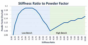
What is clear to see in Figure 4 is that two distinct actions change the powder factor based on the stiffness ratio. The first is in the low bench category and the second is in the high bench category. These two scenarios will both be explained in further detail in the following sections.
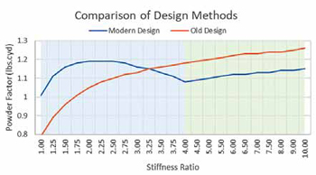
However, as Figure 5 shows, these old school techniques have not only cost operators good results from blasting with a larger stiffness ratio, but they have been costing operators much more in direct costs. From Figure 5 it is clear that with modern design approaches an operation could blast with a stiffness ratio of 4.0 and maintain lower powder factors than blasting with a 2.5 with the old approach. Better results and a smaller powder bill.
It is critical for this discussion to understand that the powder factor of a blast does not influence the fragmentation, throw, or other blast results to any major extent. Variables such as the confinement, shape of charge, timing and method of breakage are much more critical and as a result using more explosive to achieve similar or worse results is a waste of money. In the end it is not how much explosive is used, but rather the manner in which the explosive is used that achieves superior results.
Low benches are also extremely costly, not only in terms of the poor post-blast results but also in the overall borehole utilization. One of the most basic rules of thumb in blasting is that the stemming in a borehole should be approximately 70% of the burden, therefore if the stiffness ratio is low then the borehole has almost no explosive in it. This creates a large amount of drilling for a relatively small amount of explosive. This is also true with initiators, an initiator costs the same amount whether it detonates 50 lb or 500 lb of explosive, therefore using a deeper borehole which is filled primarily with explosives leads to better utilization for the cost of initiators.
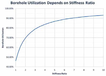
This borehole utilization is also one of the reasons that a major increase is seen between a bench with a stiffness ratio of 1.0 and 2.5. As can be seen in Figure 6, when a bench changes from a stiffness ratio of 1 to 2.5, the borehole utilization is increased by around 33% leading to a large increase in total explosives. At the same time the increase in spacing from this change is small. One can then see that to further increase from a 2.5 to a 4.0 only an 8% increase in borehole utilization exists. Furthermore, any increases above a stiffness ratio of 4.0 show incremental changes to the borehole utilization.
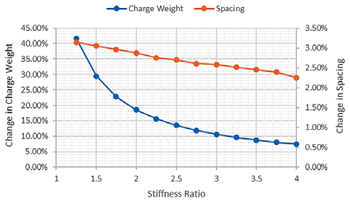
At the same time the expansion in spacing between steps of stiffness ratio remains similar, as can be seen from the orange line in Figure 7. As the stiffness ratio of a blast is increased from 1.5 to 1.75, the spacing of a blast expands approximately 3%. To further increase the spacing from 1.75 to 2.0 the spacing increases by 2.75%. While the spacing increase is slightly smaller at each increasing increment of stiffness ratio the total change is minimal, especially compared to the change in explosive weight.
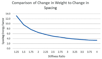
Perhaps the most simplistic way to view these changes is through what the authors have developed as a Spacing Energy Factor (SEF). This is a standardized method to view the changes from Figure 7 compared to the stiffness ratio. The SEF is a comparison of the change in weight to the change in spacing of a blast with incremental changes in stiffness ratio. At a SEF above 5.0, the powder factor is increasing as the weight of explosive increasing in the borehole has a larger effect than the increase in spacing. At a SEF around 5.0 the powder factor is remaining about the same. At a SEF below 5.0 the powder factor is decreasing. The slope of the SEF to SR graph indicates how rapidly the powder factor is increasing or decreasing.
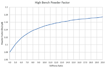
High Bench Effects
The transition between a high bench and
a low bench occurs at a stiffness ratio of
4.0. At this stiffness ratio, with proper
confinement, the cratering mechanism
ceases to exist and the borehole effect
is the primary breakage mechanism. The
fragmentation of a high bench will be better
and more uniform than that of a low
bench, the throw will be improved, the
ground vibration will be reduced, and the
spacing of a pattern will be maximized.
The effects of a high bench begin at a stiffness ratio of 4.0 and remain indefinitely. The use of higher stiffness ratios does not cause problems, until the drill hole deviation becomes a major effect on the pattern design. The minimum powder factor of the bench will be at a stiffness ratio of 4.0; where spacing is maximized, following this is a slow increase in powder factor which occurs as the stiffness ratio increases. This is due to no increase in spacing, but small increases in charge weight.
However, as the increase in borehole utilization is minimal, the powder factor increases at a slower rate and even at extremely large stiffness ratio ranges (over 15) will not reach the same maximum powder factor that a bench between a stiffness ratio of 2.25 and 2.75 would have. In fact, after a slow build up of powder factor from a stiffness ratio of 4 to 12, almost no change is observed due to the fact that the additional weight of explosive added to the longer boreholes is minimal to the explosive already in the borehole.
Case Study of Modern Blast Design
This past year the two authors completed
a project using the basic principles discussed
in this article at one of the largest
surface mining operations in the middle
east. This site was under strict government
limits on the maximum powder factor they
were allowed to use for both the overburden
and ore in order to keep costs low;
however, these powder factors were so limiting
that over 10% of ore was discarded as
oversize product and a large amount of the
overburden required secondary blasting as
the sites hydraulic shovels could not handle the boulders. The site had previously had powder representatives from local and
international companies from around the
world try to help them and none had been
able to make any changes, because they
all used old school design approaches.
The authors goal was to reduce oversize
on the ore, achieve better fragmentation
on the overburden, and maintain extremely
low powder factors.
Summary
As discussed throughout this article, powder
factor is an extremely poor design tool
that does not belong in a blasters arsenal
when approaching a blast design. At
best the powder factor is to be used as
an economic check. Old school designs
based off of powder factor and powder
factor principles have falsely led operators
to make decisions on blasting that
have not only led to poor performance of
blasts, but have also led to unnecessary
costs in excess drilling and explosives.
Modern blast design is an outcome-based
approach where the actual physics of
blasting are used to determine blast design
parameters to meet the needs of the
operator. In most cases these results can
even be achieved with less explosives
than old school design approaches.
Under old school design the ideal stiffness ratio to blast under for low cost was a stiffness ratio of 2.5; however, under modern design it is understood that this is actually the most expensive stiffness ratio to blast with. It is now understood that the most economical stiffness ratio to blast is between 3.5 and 6.0 which not only gives minimal cost but also the best performance. Todays blasting industry is far advanced from the days of load as much explosive as can be loaded and blow the snot out of the rock. It is now understood that a skilled blaster can use much less explosive and get better results than one using a larger powder factor.
Calvin Konya is the founder of Precision Blasting Services (PBS). Anthony Konya serves as project engineer for PBS. www.idc-pbs.com