Figure 1.1Minimum dilution is achieved by using the optimal equipment and
smaller ore drives for the LHOS methods.
Reducing Dilution With Narrow-vein Mining
A plan that considers drive size, blast design and quality control
provides the best results
By Paul Salmenmaki
Vein Characterization
The dilution study began with vein
characterization. The broad aim was to
identify the general variability in
vein width, geometry, and lateral extent
(strike and dip) and to identify
geotechnical conditions that
may determine the applicability
of various mining methods. The findings
included:
Consistent vein strike 1,500 m;
Vein width ranging from 0.5 m to more
than 5 m;
Ground condition ranging from poor to
good, across strike and depth extents;
Cemented rockfill and waste rock considered
to aid ground support; and
LHOS and CAF used at the mine, with
potential to optimize sublevel spacing
and mining sequence.
Optimized Dilution Scenarios
Using the results of the vein characterization
study, it was concluded that the
minimization of dilution for LHOS and
CAF would be based on:
Vein widths of 1.5 m, 2.25 m, 3.5 m
and 5 m;
Varied ore drive dimensions, and rectangular
and shanty-back profiles; and
Orebody dips of 61°, 66°, 68° and 72°.
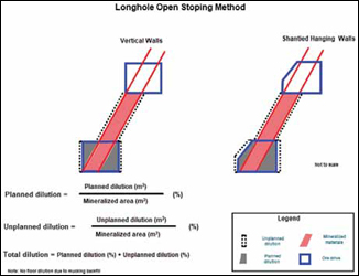
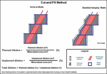
Formulae
AMC utilized the following formulae to
determine dilution. Dilution ratios were
calculated for planned and unplanned
dilution. Total dilution is the sum of
planned and unplanned dilution (Figure
1.1 and Figure 1.2). This method has
been selected from numerous alternatives
for calculating dilution.
The optimum dilution is a trade-off
against ore recovery. Given the value of
the ore for this case study, recovery was
given priority over dilution, with a target
recovery of 100%.
Equipment
AMC examined the existing fleet of
stope equipment (jumbos, LHDs, longhole
drills, and bolters) at the mine
and established optimal drill-and-blast
designs for the selected vein widths,
dips, drift profiles (square and shanty),
drift size (height and width), and
mining methods, which could immediately
be implemented to reduce dilution,
without additional equipment purchases.
AMC also identified the optimal fleet of stope mining equipment for dilution minimization. This requires the purchase of small, low-profile equipment and reduced development sizes.
Optimized Stope and Drive Dilution
AMC completed a comprehensive analysis
to determine the minimized dilution
for both LHOS and CAF using the formulae
discussed. All of the selected vein
widths, dips, drift profiles, and drift sizes
were examined to minimize dilution and
maximize recovery. The drift sizes considered
had to accommodate either existing
or optimal equipment.
In general, minimum dilution is achieved using the optimal equipment and smaller ore drives for the LHOS methods, or the lowest practicable drift heights for CAF. Minimum dilution for LHOS ranged from 66% (1.5 m stope width, 0.5 m vein width) to 9%. For a 5-m vein width, a minimum dilution of 9% is achievable in good ground with a 20-m sublevel interval and either a 5-m wide by 3-m high ore drive or a 5-m wide x 5-m high ore drive. In fair ground, the dilution projection increases to 10%. Key results for CAF method was 28% for a 1.5-m vein width and 11% for a 5-m vein width.
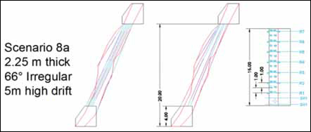
AMC used the ideal stope and drive dilution results for the basis to create drilland- blast designs, which included slot raise, production rings and powder factors (PFs) for LHOS. The drill-and-blast designs for CAF included drill patterns, suggested explosive loading and PFs. An example of LHOS design for an irregular vein shown in Figure 1.3.
Reducing Dilution
To target idealized dilution, AMC recommends
closely monitoring three areas:
drive dimension optimization, drill-andblast
practices, and overall quality control.
For the ore drives, engineers should
consider the narrower veins and purchase
equipment that fits into 2.7-m x 3-m drift.
They should also consider the use of shanty
ore drive backs. Development into orebody
hanging wall should be minimized.
Technical support processes for designing
narrow vein stopes should be reviewed.
And, when it comes to ore quality control, all departments (planning, surveying, geology, geotechnical, ventilation and operations) need to provide input and signoff for stope and mine designs. The stope markup and reference line should be set by surveyors. A surveyed drill setup process should be implemented to improve drill hole accuracy. Blasting engineers should be involved continuously with blasting crews. The cavity should be monitored and surveyed for every stope blast. Engineers need to perform regular, quantitative reconciliations between the design and the blast results. The results should be shared with stakeholders to justify implementing changes.
Paul Salmenmaki is a senior mining engineer working with AMC Consultants. He can be reached at psalmenmaki@ amcconsultants.com.