Matching Method to Orebody
Two narrow-vein project experts reveal when the mechanized raise-climber mining
method is more efficient than the long hole open-stope mining method, and when it is not
By Jesse Morton, Technical Writer
This is according to research by Ken McKirdy, chief engineer, and Tracy Kitchkeesick, technical services manager, Manroc Developments Inc., and reported at the 2018 Canadian Institute of Mining, Metallurgy and Petroleum (CIM) conference. Afterward, the former sat down with E&MJ to elaborate.
The research crunched almost two decades of data collected by the company. And it was shared at CIM and elsewhere in part as a parting gift from McKirdy, who is closing out a career at perhaps the world’s foremost Alimak mining project firm. “We’ve been doing this mining method since the early 1990s and people don’t seem to know a lot about it,” he said. “Definitely one of the things we wanted to solve was that cutoff line.”
Specifically, the research looked at data from “a couple projects per year since 2000, roughly 5.5 million to 6 million metric tons (mt) of production ore,” McKirdy said. Those projects employed either method. The data was organized on a spreadsheet. The result was “an amalgam of several projects,” amounting to a model, McKirdy said.
Kitchkeesick reported the model to be “a make-believe” orebody. It represented similar projects that differed mainly by mining method. “We used a 100-meter (m) strike mine, a 100-m vertical extent with a 65° dip, meaning there is 110 m of dip length,” she reported. The orebodies considered ranged in thickness, she reported. Each was “a uniform thickness throughout, but we looked at ranges from 1.2 m narrow up to 12 m thick,” she reported. Additionally, the orebodies considered were “dry and under a medium-stress environment,” she added.
McKirdy emphasized the importance of the last spec. “I just wanted them comparable on the stope stability method,” he said. “One of the things that affects these opening sizes is stress and what I wanted to do was set it up so that the stress was pretty similar between the two types of mining.” When filtered by method, the amalgam produced two hypothetical projects, enabling a comparison “based on tons produced per man shift,” McKirdy reported. That number, for most miners, translates to efficiency, he said.
Each project was based on some general assumptions. Both were assumed to have all the required services, “ventilation, processed water, compressed air, electrical power and base fill” and access from the main ramp, McKirdy reported. Each was assumed to tap the parent mine’s trucking, supervision and maintenance. Other assumptions were more specific to ensure an accurate comparison.
The Model LHOS Project
The hypothetical LHOS mine plan called
for “an even number of stopes over 100
m, 11.1 m each for a nine-stope level,”
McKirdy reported. “The zone strike line,
strike length and dip length were distributed
evenly among the stopes and levels.”
No major structure in the zone is assumed,
and “all diamond drill holes in
this scenario are grouted,” McKirdy reported.
“The stability number is in the
range of 1.9 to 7.1.”
Of three stope sizes analyzed, “the 23-m x 11-m long-hole open size was chosen to minimize the number of stopes, it being the least costly of the options,” McKirdy reported. The result was 36 stopes, nine wide and four high. “That is less than what we would have had if we went a little wider along the strike or with lower levels face-side,” McKirdy reported.
An access was driven parallel to strike and offset 18 m from the ore. Draw points were driven from the hanging wall access to the ore. In general, lateral development was followed by slot drilling, cable bolting, production drilling, production blasting, mucking and filling.
Specifically, the primary stope was undercut, and the secondary stope was left until the primary stopes were backfilled. The hanging wall portion of the undercut, being the new critical face, was then drilled and cable bolted. “A similar sequence is repeated for the next level up, and the slot raise can be drift divided or drilled once the stope has been undercut and overcut,” McKirdy reported.
Manpower included a leader and two miners per shift for lateral development, and then a leader and a miner per shift per active raise for slot drilling, for cable bolting, for production drilling, and for production blasting, McKirdy reported. Equipment used included a two-boom jumbo drill rig, a 6-yd3 scoop, a scissor lift, a bulk emulsion loader, miscellaneous handheld drills and pumps.
Cable bolting employed the wagon drill, scissor lift, mixer, pump and small tools. Production drilling employed the tophammer drill. “It could be the one mounted on the wagon drill,” McKirdy reported. “Stope production drilling was completed before the final slot raise blast had taken any one stope,” McKirdy said. “This is to minimize exposure to open holes.” Production blasting employed the scissor lift and bulk emotion loader “because we are loading both upholes and downholes,” he reported.
The Model MRCM Project
The initial development work for the
MRCM project was assumed to be similar.
The stopes, however, were bigger, with
the supported side of the raised stope
at 18.3 m x 110 m high. “The induced
stresses were not modeled, but we assumed
they would be comparable in the
later stages of mining for each of the different
methods,” Kitchkeesick reported.
In general, raise development was followed by cable bolting, production drilling, blasting, mucking and then paste-filling. The manpower assumed was the same as for LHOS. For initial development, “we have a leader and two miners per shift,” Kitchkeesick reported. Afterward, raise development, cable-bolting, production drilling and production blasting each employed two per shift.
Equipment included, but was not limited to, the double-drive raise climber, two boom jumbos, a 6-yd3 scoop, scissor lift, bulk emulsion loader, down the hole drill, grout mixer, small tools and pumps. Specifically, raise development, which employed the double-drive raise climber, started “with a nest and a hanging wall at the bottom of the stope,” Kitchkeesick reported. “In this case, we’ve got the nest at 4.5 m wide, 6 m high, and 18 m long.” That allowed mucking access beneath the nest. “The length of 18 m is just to keep us a safe distance away from the raise because the nest also serves as a little maintenance area,” she reported.
The raise was driven along the hanging wall of the stope. “After the breakthrough at the top level, there is a landing installed and this is for safety reasons, for people approaching, loading or leaving the climber,” Kitchkeesick reported. “With this landing in place, the raise is screened from the top down and after that the ore is painted up, surveyed, and it is then cable bolted.” The raise was multipurpose and served as a temporary access between levels, a ventilation opening, production access and blast void.
The center of the hanging wall was cable- bolted. “With the support, the stable stopes can be the foci of the ore, eliminating the need for quite a bit of development, in this case three sublevels,” Kitchkeesick reported. “We included a wagon drill in this purpose because with the wider orebodies we’ve got some cable bolting going on below in the undercut.” Production drilling was oriented 10° to 30° downward from horizontal for optimal toe breakage, making the undercut the production slot. “Production drilling is done with the raise production drill that sits on the deck of the unit,” Kitchkeesick reported.
Blasting entailed one shift per day. “With the electronic caps, we do much larger blasts, up to stopes in their entirety, which we refer to as mass blasting,” Kitchkeesick reported. With the higher strike length, less remote mucking was required. “Generally, we muck the swell from the blast and keep most of the ore in the stope so that it keeps the walls,” Kitchkeesick reported. “And then we muck it out at the end as quickly as we possibly can and that is followed with paste fill.”
The Cutoff Mark
With the projects sufficiently similar in stability
number, initial development, labor
per task, tasks per shift, and equipment
used, apples could be compared to apples.
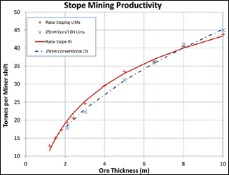
The total number of man shifts and the
resulting metric ton per man shift were calculated
and plotted “against ore thickness,
using the results we got for each different
mining method,” Kitchkeesick reported.
The number of man shifts were determined by taking “the days per task, the crew size per task, and the amount of tasks per number levels,” McKirdy reported. “This is repeated for each thickness.” For LHOS, “we came up with about 18 mt to 50 mt per man shift, depending on the ore thickness,” McKirdy reported. For MCRM, the results differed slightly. “We did go down a little bit narrower just because we can,” Kitchkeesick reported. “For 1.2-m-ore-thickness, we had 12.9 mt per man shift up to 45.5 for the 12 m thickness.”
On the resulting chart, the productivity lines for each method run parallel upwards, with MRCM slightly above LHOS until the two intersect a bit below 10 m. “Anything under 8 m, assuming the four sublevels, it is more efficient to do the raise mining,” Kitchkeesick reported. Additional development and sublevels moved the point upward. “Obviously, the more sublevels you have, the more applicable raise mining is,” she reported.
And the four-sublevel project was more ideal than practical, McKirdy said. “You want to minimize the number of stopes if you can, which generally means making them larger,” McKirdy said. Accurate drilling, in a perfect world, maxes out at around 25 m and is the limiting factor. Rare are 25-m stopes, he said. “More likely you would do 20 m, five rows of stopes high.” That additional row requires additional man shifts, driving down efficiency. “There is an optimum stope size, and then you start adding the number of stopes, so you add ventilation changes, you add backfill dams, you add slot raises,” McKirdy said. “So it is the preparation.”
At five sublevels, the cutoff point climbs to 11 m. At six, it is 13 m, Kitchkeesick reported. MRCM is also more efficient in instances where access is limited and reaches only “isolated little islands of ore,” McKirdy said. In those cases, the miner can “either do it blind, or you can drive a sublevel and an extra raise,” he said. “Most of those are so short that we (MRCM) then blind and blast them with i-kons.”
Nonetheless, it is the 8-m cutoff point that McKirdy said is generalizable enough for quick calculations, brainstorming and informal planning. “If you had a tabular, steeply dipping orebody that was less than 8-m thick, you’d look at Alimak raise mining,” he said. “If it was thicker, then it might be reason to look elsewhere.”