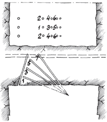
Figure 1Fan Cut Diagram (Olofsson, 1991).
Modern Design of Fan Cuts
Understanding the principles allows more effective use of the fan cut
for slashing and crosscuts
By Anthony Konya, Calvin Konya and Paul Worsey
The fan cut allows for relief to quickly and easily be made as the hole angles are quickly transitioned into straight in holes. Because of the geometry, smaller drifts can be mined with a fan cut because a drill can be set up in the middle or far side of the round and the fan portion of the cut can be placed on the opposite edge of the face.
In general, fan cuts are more common in smaller drifts than V-Cuts that do not require as fine fragmentation as obtained with burn cuts. The face advance of a fan cut will be between 40% to 60% of the width of the tunnel (Langfors & Kihlstrom, 1967).
In the traditional design, the fan cut is laid out to blast a horizontal slot across the face, three holes high. The rest of the round above and below is drilled straight in. This was due to the use of older equipment, such as jackleg drills and the difficulty of drilling angled holes precisely using the older equipment especially at extended heights.
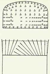
Langefors and Kihlstrom (1967) give multiple examples of double fan cuts one of which is illustrated in Figure 2, which when initially viewed appear similar to a V-Cut with the central portion between V holes fanned from one side, the V being to the opposite side and its axis skewed at an angle toward the center.
It is interesting to note that the cut as in traditional V design is used to develop a horizontal slot to provide relief for the rest of the round, which uses straight holes.
Traditionally, the fan round was used to mine smaller drifts. However, in modern mining with the use of large jumbo drills, the technique is primarily used for starting crosscuts off a main heading.
With modern explosives, a traditional fan cut as illustrated in Figures 1 and 2, can lead to pre-compression or dead pressing of the explosives as discussed in previous articles (Konya, Konya, & Worsey, Modern Underground Blasting Methods, E&MJ June 2017). This can result in very poor performance to complete freezing of the fan cut if some of the early fan holes fails to fire.
Modern Fan Cut Design
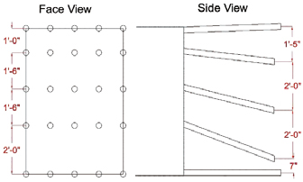
In a more modern design, the fan cut is extended from floor to
roof, which is made possible using high-reach drilling equipment,
thus extending it to a fan round rather than just cut.
The fan round comprises a single-sided fan and larger diameter
boreholes are typically used, which increases the distance
between boreholes reducing the risk of dead pressing
and pre-compression.
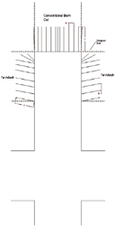
Whereas in the old days, this was very easy for a jackleg drill to accomplish. Because of this, an operation that drills headings using burn cuts has to slash the rib to start a crosscut (or work around a pillar) as illustrated in Figure 4, until the opening is sufficiently large enough to allow the rig to drill, at which point the burn cut can be used again.
An artists rendition of the drilling process is given in Figure 4. The pillars and crosscuts are shown with the advancement, with burn cuts going forward and slashing rounds starting crosscuts.
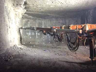
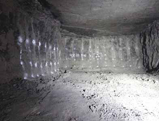
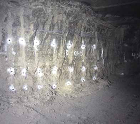
An example of a modern slashing round is illustrated in Figures 5 and 6. In Figure 5, the round in the heading looking forward is a standard Doe Run burn cut with four relief holes. A fan/slashing round is drilled to the left to start a crosscut. In many cases, up to three rounds are drilled and charged in the same heading and if there is a cutoff of one of the rounds the entire hook up on the face of that round will is obliterated by the neighboring rounds causing difficult recovery and a lot of lost time. At Doe Run, the holes are primed with long-period (LP) shock tube delays clipped onto detonating cord ring mains.
To avoid the potential for a cutoff, separate detonating cord lead-in lines to each round have been implemented and the ring mains are also tied together with detonating cord jumpers for redundancy. This is a very important best practice.
The convention for underground for many operations is to use LPs to allow time for movement. However, millisecond delays can be used just as easily, and in many cases will provide superior fragmentation because of the small burdens compared to bench blasting in quarries. In general, the rounds are fired at the same time with the same delays. The perimeter (pillar) holes of the burn cut round being on high delay numbers are fired well after the first holes in the slashing/fan rounds, which are fired on low delay numbers and this protects the pillar corners.
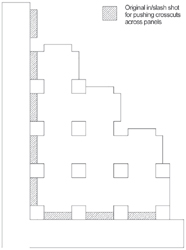
The metal deposit at Doe Run is lead-zinc-copper and is not regular in shape, therefore the use of the slashing round is quite common. However, in massive regular room-and-pillar mining, which is used in underground limestone mines, the slashing round only has to be used to start crosscuts from the most advanced heading. Once crosscuts are established the regularly used blasting techniques of burn or V-Cut can be used to extend each cross cut throughout the mine as illustrated in Figure 7.
Hammer Cuts
The fan cut can also be turned 90° to where the angled boreholes
are going toward the floor and then used with either lifter holes or an undercut. This is traditionally called a hammer cut
and follows similar design principles as the fan cut.
The hammer cut is now a rarely used method for underground heading design as the angles are difficult to achieve especially with modern large drilling equipment. However, it can be implemented in drifts that are tall and too narrow to allow for the full fan cut. Drill deviation and drill depth then become critical for ensuring toes are not left on the floor.
Calvin Konya is the founder of Precision Blasting Services (PBS). Anthony Konya serves as project engineer for PBS and Dr. Paul Worsey is a mining professor and well-known explosives expert and researcher at the Missouri University of Science and Technology. www.idc-pbs.com
References
Konya, A., Konya, C., & Worsey, P. (2017, June). Modern
Blasting Method Selection. Engineering and Mining Journal,
44-51.
Konya, A., Konya, C., & Worsey, P. (2017, September).
Modern V-Cut Design. Engineering and Mining Journal,
40-42.
Langfors, U., & Kihlstrom, B. (1967). Rock Blasting.
Sweden.
Worsey, P. (2017). V-Cut and Fan Cut Design, Section 6.3.
Underground Heading Design, Missouri S&T Course Explosive
Engineering 5622 Blasting Design and Technology.
Rolla, Missouri.
Olofsson, S., 1991, Applied Explosives Technology for Construction
and Mining, APPLEX, ISBN 91-7970-634-7.
Konya C., 1995, Blast Design, IDC, ISBN 0-9649560-0-4.
Note: Dr. Worsey has provided blaster training at Doe Run for
several years.