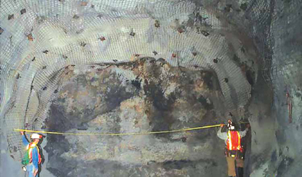
Miners spray on an initial early-strength shotcrete layer with fibercrete (poly or metal). The goal is to
stabilize the immediate rock zone followed by placement of primary support of mesh and bolts.
Design Considerations for Ground
Support in Nevadas Weak Rock
A new analysis demonstrates how the use of bolts, mesh and shotcrete influence the
safety factor for ground support programs
By Jesse Morton, Technical Writer
The example drift is 14 ft (4.3 meters [m]) wide. The report described it as situated in ore of the Type IV and Type III weak rock class categories that necessitate the use of bolts, mesh and 2 in. to 4 in. of shotcrete. Sandbak described it as very weak. We could have ground that we have standup times of almost immediate collapse to hours or days, he said. If it didnt have any support it would just collapse or cave.
Five years ago, the original drift size was 10 ft by 10 ft. Initially, drift support plans discounted shotcrete and mesh. All of our safety factors that we based our drift size on were based on bolts only, Sandbak said. Nonetheless, the mine was logically using shotcrete and mesh as the drift widened and the company sought to deploy more equipment and automation. In our weakest rock, shotcrete seems to do better in some cases if we can confine our ground with it, he said.
The goal was to arrive at an equation, a formula, that determines how many bolts, and how much shotcrete and mesh, are needed for a specified area to have a minimal safety factor of 1.5. Sandbak presented the findings in Safety Factor Design Analysis: Integration of Bolts, Mesh, And Shotcrete Support in Weak Rock Masses, Turquoise Ridge Mine, Nevada at the 2017 Society for Mining, Metallurgy and Explorations annual conference in Denver (see SME preprint No. 2017-110). It proved not only the importance of shotcrete for retention purposes. According to the report, shotcrete and mesh can be critical for support in certain types of rock.
The report takes the reader to this conclusion after looking at the current research on the topic. First, it reviews how the safety factor is gauged for drift support using only bolts.
Bolts Only
To attain the desired safety factor using
only 8-ft bolts, the key variable is the quality of the rock, the report stated. The
support capacity of the system is determined
by the bond strength of the bolts
holding up the wedge, which is in turn
based on the Rock Mass Rating (RMR).
Bond strength of a bolt will vary from mine to mine. In strong rock, bolt bond strength is greater. For high RMR, each foot of bolt can support a greater volume of rock, Sandbak said. For RMR less than 25, classified as very poor to poor rock, were only going to give it one ton per ft, he said.
Easiest to envision is bolt support in strong rock, Sandbak said. In strong ground they can get double or triple the strength, so you dont need as many, he said. Bolts can only hold so much in weak ground.
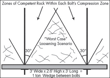
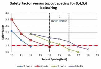
The equation seems simple when supporting high RMR rock. Superficially, it would require only adding together the individual bolt values. In low RMR rock, however, the bond strength is low. As the drift widens, each additional bolt can support less rock. Pretty soon, its got a diminishing return because it is a volume thing, Sandbak said. A 10- by 10-ft drift in low RMR might require only three bolts in the back. For a 12 by 12 we needed four bolts, he said. As we go out to 14, or anything larger than 14, we went to six bolts. (See Figure 1.)
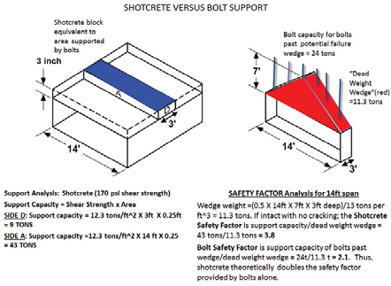
The volume of rock to be supported would be greatest in the center of the drift. Turns out, according to the report, theoretically the values for the center bolts would be less than that of a 3-in. wedge of shotcrete.
Bolts, Shotcrete and Paper
On paper, in certain types of rock, shotcrete
can play more than its traditional
role. Calculations reveal that it can serve
as primary support. The support capacity
of shotcrete is equal to the shear
strength times the area affected, the report
stated. Presuming ideal adhesion, a
3-in.-thick, 3-ft-wide by 14-ft-long wedge
of shotcrete in the back has a support capacity
of 43 tons if this slab could remain
intact, the report stated. Therefore, the
calculated safety factor of shotcrete is
3.8, or nearly doubles that of the safety
factor of using bolts. (See Figure 2.)
The report states shotcrete does not adhere well to certain types of low RMR rock. In those types, it would primarily be used for retention. In higher RMR rock, however, if you just go by the sheer strength, that little box of shotcrete, is better than that entire bolting sequence of six bolts in that same 3-ft wedge, Sandbak said.
Cracking Up
Shotcrete by itself is vulnerable to load
displacement due to rock movement. If the
rock it supports shifts a few millimeters,
it could crack or worse. When that happens,
it would lose its supportive qualities.
Shotcrete is relatively weak in tension,
and after significant cracking loses 80%-
90% of its strength, the report stated.
There are a number of ways shotcrete can fail. Failure mechanisms of sprayed shotcrete includes adhesion, a punching through shear failure, flexural failure, and flexural shear failure, the report stated. As mentioned, sometimes shotcrete wont adhere to weak rock with lots of clay. Sometimes you might have shear and it punches through in between the bolts, or as a flexural failure it squeezes and it shears, Sandbak said. If you get stress between the bolts, it could crumble and form its own thing and fall out as a flexural failure. If you get a lot of movement, it could shear to the bolts and then fall out.
On paper, once shotcrete cracks it loses its support capacity, Sandbak said. As soon as it breaks and cracks, they give shotcrete zero support. It is no longer viable, he said. In practice, however, if used in conjunction with or behind mesh, it still provides some support. It is weak, he said, but if you combine it with mesh or combine it with fiber or anything else, it gives you more. It is not zero anymore after it breaks.
Therefore, shotcrete should be reinforced with mesh. Bolts provide confinement and compression, the report stated. And mesh restricts the bulking of the rock mass, and ensures the interlock friction to keep the rock mass in compression.
For some drifts, shotcrete alone will provide sufficient support. In really strong ground you could do shotcrete by itself and it would probably do it because it wouldnt crack, Sandbak said.
However, for use at Turquoise Ridge, where the tests were conducted, its theoretical value gets reduced by almost an order of magnitude. Shotcrete is only utilized in that weak ground at only 17% of what they claim originally that strength would be, he said. Shotcrete doesnt provide the best support here by itself because it doesnt stick very well.
Test results captured this reality. In a lab, shotcretes calculated support capacity is 170 pounds per square inch (psi), the report stated. In actual tests from Turquoise Ridge, the adhesion strength of shotcrete tested is approximately 145 psi or 1 megaPascal (MPa) after 30 days, it stated.
At Turquoise Ridge, shotcrete is used for retention. Thanks to the testing conducted there, an engineer elsewhere can calculate the support capacity of shotcrete based on the RMR of the rock it will support.
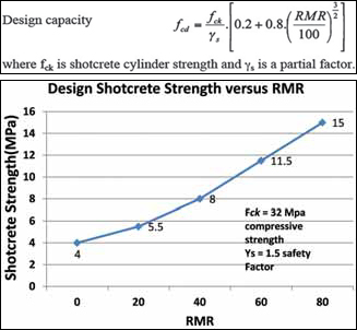
The Equation
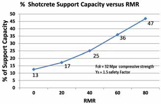
As mentioned, the report puts the shear
strength of shotcrete partially confined
by mesh and supporting low RMR rock
at 17% of the calculated support capacity.
As the RMR increases, the shotcrete
capacity increases from 13% for the lowest
RMR to 50% when the RMR is 80,
the report stated.
Adding mesh provides additional support in case of load displacement due to movement. Even after it has moved several inches, mesh is still providing support, he said. After it cracks, yes it does lose some support. In our case, it is combined with mesh so we get some retraining elements.
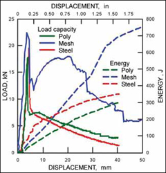
Mesh proves to be critical in supporting shotcrete in rock prone to movement, the report said. Shotcrete reinforced with mesh will resist cracking and have a higher residual load in displacement environments than fiber-reinforced shotcrete, the report stated. The energy absorbed is also much higher for the mesh at 700 joules versus 300 joules for the poly or metal fibercrete.
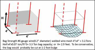
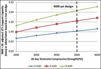
This is because the mesh provides the tensile strength shotcrete lacks. Mesh combined with shotcrete give you the best of both worlds, Sandbak said. Turquoise Ridge uses No. 6 mesh screen. It provides about 3.3 tons (of bag strength), or a local safety factor of 3.3, the report stated. (See Figure 6.) The current thickness of shotcrete (3 in.) at the current 5,000 psi compressive strength is expected to provide another 1.5 tons of support or a safety factor of 1.5. (See Figure 7.)
Going Forward
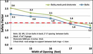
Combining mesh and shotcrete increases
the overall safety factor by at least 0.4
for the 14- by 14-ft top cuts, and 0.2 for
the larger sized drifts, the report stated.
This suggests that a 15- by 15-ft topcut
with the allowable 2-ft-wide overbreak
is still above the safety factor of 1.5, or
the addition of shotcrete gives us more
leeway on allowable overbreak to near 18
ft. (See Figure 8.)
Fundamentally, the local safety factor is gauged to keep the area between the bolts intact, Sandbak said. Once it unravels, the larger wedge is going to come out, he said. With shotcrete and mesh, we retain that really high safety factor between the bolts.
Sandbak said that the report reveals the viability of an unconventional strategy. Shotcrete has always been viewed as secondary support: something to coat the wire mesh to prevent small rocks from falling out, he said. The objective going forward is to try to spray shotcrete first, and then place bolts and mesh on top of the shotcrete. Ideal, he said, would be to get an early strength shotcrete of at least 150 psi (1 MPa) in one hour so as to limit initial movement, and facilitate the drilling for bolts without unravelling the shotcrete or rockmass.