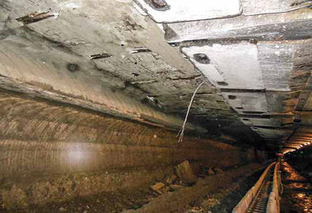
The view from Chute No. 1 after complete cut-through with longwall face in final
stop position.
Signal Peak Energy Makes Longwall
Recovery History
A western U.S. coal mine uses a cuttable concrete in a predeveloped recovery entry
to remove shields
By By Brad Hanson, Robert Ochsner, Dr. John C. Stankus and Dr. Xiaoting Li
To retrieve the shields at the end of a longwall panel, the Bull Mountains mine No. 1 employed a traditional recovery entry in the 1 Right panel and predeveloped recovery entries in 2 and 3 Right panels. For a new mine with specific geological conditions, it was difficult to accurately predict the behavior of the roof strata when the longwall face approached the recovery entry. The lessons learned from the 1 and 2 Right recovery entries enabled mine management and Keystone Mining Services (KMS) to work together and design an effective roof support plan for the 3 Right recovery entry. The success of the 3 Right recovery entry created a record for retrieving the shields within 15 days, not to mention the safest working environment for protecting miners.
Geologic Conditions and
Recovery Experience
Every mine has its own geological characteristics,
and the Bull Mountains mine
has two unique geological features that
many other longwall mines do not have:
low overburden and a distinct pattern of
roof joints. The overburden above the
Mammoth coal seam in the 1-3 Right
recovery areas is approximately 200 ft
thick. The roof consists of shale, siltstone/
sandstone and rider coal (Rehder coal
seam). The location of the Rehder seam
changes, and when it comes close to the
roof line, roof instability may occur if sufficient
roof support is not installed.
When recovering the longwall face from the first two panels, the mine experienced adverse roof conditions. In 1 Right, a 20-ft-wide conventional recovery was attempted, but ended up being 12 ft wide from the shield tips to the outby coal rib. Additional wood cribs and steel beams were installed, reducing the entry to 9 ft. A roof shear with an angle of 5°- 9° from the vertical occurred, and broken roof rock applied significant loading on the shields. The broken rock reached a height of approximately 20 ft above the roof line.
The abnormal roof conditions in 1 Right recovery entry can be first attributed to the delays associated with installing roof support in the recovery entry. Within this period of time, a rock cantilever formed above the shields and rotated due to the easily caving gob. Over time, the rotational movement of the cantilever beam induced an angled shear near the outby rib line of the recovery entry. Surface fractures and subsidence appeared very soon (see Figure 1).
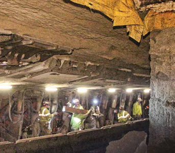
The predeveloped 2 Right recovery entry was 30 ft wide, and in addition to cable bolts, was supported with three rows of 24- and 36-in. diameter, cuttable, pumpable cribs within the recovery entry and one row of 30-in. diameter, non-cuttable, pumpable cribs on the outby pillar side. Problems installing the recovery mesh over the shields caused significant delays, which allowed the roof to deteriorate, and significant loading occurred due to load transfer from the fender pillar to the pumpable cribs in the recovery entry and shields on the face. The fender pillar refers to the narrow pillar of coal between the longwall face and recovery entry. Approximately 24 in. of roof convergence was measured in the recovery entry after the fender pillar yielded. Prior to this convergence, large pieces of rock fell in front of/above the shield tips (see Figure 2), which significantly slowed down the advancement of the longwall face.

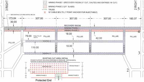
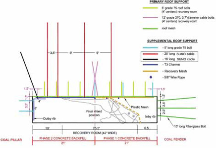
A 5- and 7-ft-long, 0.804-in. diameter J-Bar, grade 75, fully grouted bolt was installed as primary support along with wire mesh in the recovery entry. As supplemental support, 25- and 16-ft-long, 62-ton capacity, 1.10-in.-diameter sumo cable bolts along with 20-ft-long T3 roof channels were installed. The cable bolts were fully grouted with a thixotropic grout after initial installation with a normal 4- ft resin cartridge. To reinforce the outby rib, a roof/rib angle channel along with two, 5-ft-long J-Bar, grade 75 bolts were installed. In the transition zone between Phase 1 and Phase 2, two cross-installed cables were installed to reinforce the roof beam (Figure 4). The roof Reinforcement Density Index (RDI) was calculated to be 1.62 MPa/m.
In the chutes, two rows of 25-ft-long, fully grouted, 62-ton-capacity sumo cable bolts were installed along with a 30-ton cable truss system as supplemental support.
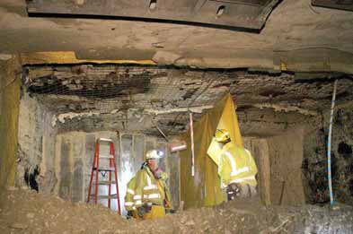
Inspections to confirm full contact of the concrete to the roof were conducted using boreholes and cameras along with inspection pipes installed at the top of the forms and bulkheads. Observations were made of the phase 1 backfill contact to the roof during phase 2 mining. If voids were encountered, they were filled with polyurethane (PUR). Mining would not continue until the PUR was cured with a minimum UCS strength of 800 psi.
Ventilation was provided across the top of the entire backfill until the final lift was poured and the backfill was completed. A minimum air flow rate of 6,000 ft3 per minute (cfm) was maintained.
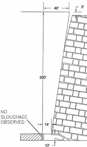
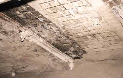
After the last cut of concrete in the recovery entry, a 1- to 2-ft thick portion of concrete was left on the outby pillar rib. No indication of stress or roof/rib sloughage was observed in the face or chutes after the cut-through. The concrete/ coal pillar corners remained sharp with absolutely no signs of pressure (see Figure 6).
Shield leg pressure graphs within the last 63 passes indicated two loading events; i.e., an increase of shield leg pressures. The first loading event occurred when the coal fender narrowed down to 6 ft wide, with some shield leg pressures increasing to greater than 6,800 psi. This loading event was due to load transfer from the fender pillar to outby concrete and inby shields. The shield leg pressures returned back to normal when the roof rock caved behind the shields, indicating a pressure release.
Also, when only 4 ft of concrete remained and the shields were in the final position, some shield leg pressures increased higher than 6,800 psi. This indicated that most of the load on the concrete transferred to the outby pillars, and part of load to the face shields. These shield leg pressures returned back to normal again when the roof rock caved behind the shields. Moreover, shield leg pressures indicated that the shields in the middle and tailgate side of the face incurred much higher leg pressures than those at the headgate side. This was due to the fact that the loading condition, because of gob on both sides, was higher than the headgate side (one side gob, other side solid panel).
The measured surface subsidence contours indicated that 5 ft of surface subsidence was measured 210 ft inby the 3 Right recovery entry. The surface subsidence values decreased toward the recovery entry with 1 ft of surface subsidence directly above the middle of the recovery entry.
Plans for Future Recoveries
The 3 Right predeveloped recovery entry
was designed based on the experience
gained during the 1 Right and 2 Right
recovery entries and specific geological
and mining conditions, especially the
low cover and joint-prevalent features.
The successful cut-through of 3 Right
recovery entry can be mainly attributed
to the: (1) completely backfilled lowdensity
concrete, and (2) pre-installed
primary and supplemental bolts, along
with a T3 roof channel, and steel and
nonmetallic recovery meshes, fiberglass
bolts in the inby pillar, steel rib bolts in
the outby pillar, and angled roof/rib
channel. This roof support system controlled
the roof joints and associated
loading condition, effectively transferred
the abutment stress, eliminated the time
delay associated with installing recovery
mesh and bolts on the face, and provided
the miners a very safe environment
for recovering the longwall equipment.
Based on the analysis of the 1, 2, and 3 Right longwall recoveries, the support design for the 4 Right predeveloped recovery will basically be kept the same. Some possible minor changes include: (1) adjustment of the low-density concrete strength, (2) adding an additional recovery chute, and (3) modifying the type and/or length of some bolts, especially in the transition zone of the Phase 1 and Phase 2 concrete backfill.