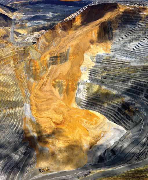
This post-slide photo provided by Kennecott Utah Copper shows how the 2013 Manefay slide damaged infrastructure and
changed the size and shape of the century-old Bingham Canyon pit in minutes.
Recovering from Bingham Canyon’s Record-setting 2013 Slide
Rio Tintos Utah copper operation rebounded rapidly to regain full production
By Russell A. Carter, Managing Editor
By February 2013, the mine knew from ground-movement data—collected from a 220-prism network, extensometers, time domain reflectometry, microseismic array, IBIS and GroundProbe slope stability radars—that a slide was inevitable and imminent. What surprised everyone, when it finally occurred at 9:30 p.m. on April 10, was its overall size and scope, involving an estimated 147 million tons of material that buried more than 95% of the pit floor under 100–400 ft (30–122 m) of dirt and rock. In just minutes, the slide drastically changed the size and shape of the pit, covering much of the exposed ore zones and rendering production plans and schedules almost useless. The slide route extended 2,400 vertical ft (732 m) down the pit wall, created an escarpment up to 400 ft high at the top of the slide, and left a 20-millionton block of rock in place on the pit rim, perched on the fault line and subject to failure at any time.
It also tore out a 1,500-ft-long section of the main haul road—known as the “ten percent” road and the only major route in and out of the pit—and buried 13 haul trucks, three rope shovels and 60,000 lb (27, 215 kg) of diesel fuel stored at the pit bottom. It essentially split the production fleet into two groups: equipment that was stranded below the damaged section of the main haul road, and equipment that was located above the damaged road segment.
Because of extensive monitoring and preparation prior to the slide, the mine evacuated workers and some equipment from threatened areas well before the disaster took place, and no one was injured. The in-pit crusher, crusher ore conveyor, and conveyor tunnel to the Copperton concentrator stockpile shed were undamaged by the slide, and critical power lines and the pit’s cellular service tower had already been relocated out of the slide’s estimated impact area. Prior to the slide, study teams realized that access to the pit bottom would probably be lost when it eventually occurred—but equipment would still be needed to attack the slide from the bottom. A number of trucks, shovels and other equipment were prepositioned on the pit floor in an area that was thought to be safe from the slide, and a new maintenance pad and a fuel storage area also were installed there—only to be buried by the unexpected volume of slide material. The slide also destroyed the “6190” truck maintenance facility higher up in the pit.
Early estimates of how long it would take the mine to recover from the slide were grim, some reaching as far into the future as a year or more for remediation—at a potential revenue loss of $5 million for each day ore could not be delivered to the concentrator. However, a remarkably well-coordinated and timecritical recovery effort brought the big mine back to life in a hurry, with overburden removal restarting in unaffected pit areas three days after the slide and haulage of stockpiled low-grade ore to the concentrator’s active storage building under way three days after that. Seventeen days after the slide, the mine began delivering newly mined ore to the concentrator. Members of the planning, engineering, procurement and logistics teams that carried out the recovery program presented details of the effort earlier this year in two technical sessions at the 2014 SME annual meeting and exhibit in Salt Lake City, Utah.
Rapid Recovery Plan Faced with buried, damaged and stranded production equipment, dangerous slope conditions, lack of access into or out of the pit, and an idle concentrator with a gargantuan appetite for ore, the teams tackled the two biggest problems first: making the pit safe for workers and equipment; and acquiring a new fleet of major earthmoving equipment to replace the buried or damaged units. The urgent need for new equipment launched an incredibly rapid procurement campaign involving more than 90 pieces of large equipment, including two new shovels, 30 bulldozers, nine hydraulic excavators, 20 haul trucks and three blasthole drills.
Once acquired, the equipment had to be assembled, commissioned, and deployed to support remediation earthmoving and eventually restart mining in the lower portion of the pit. Several items of equipment assigned to remediation were configured for remote control or autonomous operation to conduct dozing, excavation, and drilling in areas of the pit and slide path deemed too dangerous for personnel to enter. Various control systems were employed, including those from ASI on some smaller excavators, Caterpillar Command on dozers, and TORC Robotics on haul trucks and a larger excavator. Four blasthole rigs were assigned to autonomous or teleremote drilling duties, including an Atlas Copco PV275, PV271, DML and Sandvik D90.
The mine received permission from the U.S. Mine Safety and Health Administration (MSHA) in May 2010 to use the remote-controlled equipment in the remediation effort, and a multipronged attack was launched to: 1) Clean up the “head scarp”—the mass of material perched at the top of the slide scar—and other hazardous areas along the upper slide path; 2) Repair the “ten percent” haul road to provide high-traffic access to the lower pit; and 3) Clean up benches covered by the slide and get back “into ore” to ramp up production.
Studies prior to the slide indicated that one pit-bottom access route would still be available even in the worst slidedamage scenario—a narrow, steep, lightduty road known as the Keystone access, with 13 switchbacks and 10%–15% incline. After the slide, the Keystone road became the main thoroughfare for moving workers, materials and machinery to the pit floor, but its less-than-perfect layout posed major logistical problems. The mine converted a 40-ton-payload Volvo Construction Equipment A40 articulated dump truck to a flatbed transporter capable of navigating the route, but still had to frequently dozer-push and pull custom-built skids loaded with major equipment components down the road for assembly at the bottom—the most notable among them, a 12- x 30-ft, 120,000-lb structural section for a Hitachi 5600 excavator, which was completely assembled in the cramped area of the pit floor not impacted by the slide. Overall, roughly 20,000 trips were made up and down the Keystone road for parts deliveries, worker transport and other purposes—without incurring any significant traffic-related incidents.
Elsewhere around the mine, expedited equipment delivery and assembly was under way to support and meet a selfimposed November 2013 deadline for finishing certain remediation projects that would allow mining to restart in some parts of the pit affected by the slide. As examples of the hectic pace, a P&H 4100XPCAC rope shovel was bought, shipped, assembled and commissioned 90 days from purchase order initiation; and Komatsu haul trucks were being assembled onsite at a rate of four per month.
Remediation-project milestones began to appear and rapidly disappear as work on the slide gained momentum; in August, the MSHA approved the start of manned work in the slide run-out zone; the “ten percent” main haul road into the pit was restored in late October; and remediation of the pit’s current ore sector was completed in November. In December, the mine said it had reached the goal of 165,000 t/y concentrate production. KUCC noted that the mine had averaged 126,000 tons of material moved per day from the date of the slide, with average production levels during that period higher than pre-slide averages.
Rocking the Record Book In January, University of Utah scientists reported that the Manefay slide was the biggest nonvolcanic slide in North America’s modern history. It included two rock avalanches that happened 90 minutes apart and triggered 16 small earthquakes, according to data recorded at the school’s seismograph station.
The landslide, which moved at an average of almost 70 mph and reached estimated speeds of at least 100 mph, left a deposit so large it “would cover New York’s Central Park with about 20 m (66 ft) of debris,” the researchers reported in the Geological Society of America magazine, GSA Today.
The scientists said that earthquakes regularly trigger landslides, but the Bingham Canyon slide is the first known to have triggered quakes. The slide occurred in the form of two rock avalanches at 9:30 p.m. and 11:05 p.m. Each avalanche lasted about 90 seconds. While the slides were not quakes, they were measured by seismic scales as having magnitudes up to 5.1 and 4.9, respectively. The subsequent real quakes were smaller.
Risk management is a serious part of the business these days, says Dr. John Read, a CSIRO senior manager who leads the organizations coordination of the
industry-wide
large open-pit mine slope
stability project. Companies make huge investments in these mines and the mines are also huge.
Recovering from Bingham Canyon’s Record-setting 2013 Slide
Rio Tintos Utah copper operation rebounded rapidly to regain full production
When CSIRO Senior Manager Dr. John
Read brought together a group of industry contacts at a conference in
Santiago, Chile, in 2004 to sound out
the idea of pooling knowledge of openpit mine stability, he was pleasantly
surprised with the reaction.
The contacts, representing major mining houses, backed his idea, providing the genesis for what is now known as the large open-pit mine slope stability project.
“There was immediate support from the group for a shared and better understanding of the geological interactions associated with rock mass failure and recognition of the need for new guidelines for reliable slope design,” Dr. Read said.
The project addresses an industrywide need to improve understanding of the relationship between the strength and deformability of rock and the likely mechanisms of failure in large open-pit mines. It includes innovative geomechanics research, such as 3-D structural modeling, and is helping mine managers minimize the risk of loss of life, equipment damage and sustained production losses in the event of slope failure.
The project is coordinated by CSIRO and sponsored by 12 mining companies (see sidebar on page 50) representing much of the world’s base metals and diamond production. CSIRO is Australia’s national science agency. Sponsor companies are Barrick Gold, BHP Billiton Innovation Pty. Ltd., Codelco, Compania Minera Dona Ines de Collahuasi SCM, DeBeers Group Services, Newcrest Mining Ltd., Newmont Australia Ltd., Glencore Queensland Ltd., Debswana Diamond Co., and Rio Tinto.
By the end of this year, CSIRO and its partners will have produced four books to guide professionals such as geotechnical, mining, and civil engineers and hydrogeologists in the investigation, design and construction of stable rock slopes.
Chapters are written by the people regarded as having the most expertise in each area—often from the sponsor companies.
The first book, Guidelines for Open Pit Slope Design(2009), links project research with best practice in open-pit data collection and management; slope design, management and monitoring; and mining and risk management.
“The book outlines how you collect reliable data, prepare a geotechnical model, use data for stability analysis, apply that in mine development, and monitor the performance of the mine slopes,” Read said. “Failures will always happen, but what we’re trying to do is help manage the risk and diminish the likelihood of having a major failure.
“Companies can do this by having better design and monitoring practices to keep an eye on what’s going on, especially with slope management and the development of pore water pressure within the rock mass.”
The sponsor companies each provided $100,000 a year for the research, publishing and project coordination. Dr. Marc Ruest, De Beers Global Mining’s group lead of geotechnical and hydrogeology, said the project has been a long-term commitment that has been extraordinarily collaborative.
“De Beers has benefited significantly from the large open-pit project in so many ways. CSIRO has effectively brought together engineers from mining houses around the world to develop a common ground in the critical geotechnical design and implementation issues at our mine,” Dr. Ruest said. “The guidelines developed as part of the project continue to provide our practitioners with a high-quality baseline for the geotechnical programs at our operations.”
Read said the guidelines have helped mine managers become more aware of the need for reliable data and how to assess that data. It has also improved their understanding and assessment of rock mass strength and how to use that information to better analyze rock stability. This has helped them maximize safety, ore recovery and financial returns over the life of the mine.
“Risk management is a serious part of the business these days,” Read said. “Companies make huge investments in these mines and the mines are also huge. Some of the pits are up to 1,000 m deep—Chuquicamata in Chile for example, and some of the walls will be up to 1,400 m high, such as at Pelambres, also in Chile.”
The book is widely used. “You can find it on the desks of the geotechnical people at pretty much every mine site you care to go and visit,” Read said.
A second book, on open-pit design and water, was published early this year, expanding on a chapter in the original guidelines (see sidebar). Read said it provides mine managers with improved information on assessment and monitoring of pore water pressure in closely jointed rock, and how to incorporate this information into stability analyses. The first two books area available in hard copy and e-format from CSIRO Publishing (www.publish.csiro.au).
A third book, Guidelines for Open Pit Design in Weak Rocks, and a fourth, Geotechnical Guidelines for Mine Waste Dump and Stockpile Design, will be released later this year.
At a meeting in Brisbane last September, the sponsor companies decided unanimously to continue the project in some form, even though it is due to be completed in June, when Read’s own involvement in the project will end.
This article originally appeared in Resourceful, CSIRO’s magazine covering the minerals value chain.
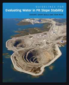 CSIRO said Guidelines for Evaluating Water in Pit Slope Stabilityoffers slope design practitioners “a road map that will help them decide how to investigate and treat water pressures in pit slopes. It provides guidance and essential information for mining and civil engineers, geotechnical engineers, engineering geologists, and hydrogeologists involved in the investigation, design and construction of stable rock slopes.” The publisher’s description of Guidelines for Evaluating Water in Pit Slope Stabilityrefers to the book as “a comprehensive account of the hydrogeological procedures that should be followed when performing open-pit slope stability design studies…this book expands on the hydrogeological model chapter in the LOP project's previous book Guidelines for Open Pit Slope Design.” The book comprises six sections, which outline the latest technology and best practice procedures for hydrogeological investigations. The sections cover the framework used to assess the effect of water in slope stability; how water pressures are measured and tested in the field; how a conceptual hydrogeological model is prepared; how water pressures are modeled numerically; how slope depressurization systems are implemented; and how the performance of a slope depressurization program is monitored and reconciled with the design. |