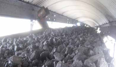
Figure 1—Overloaded coal conveyor.
How to Increase Conveyor Capacity
Start by boosting belt strength, then consider wider belt widths, higher belt speeds, optimizing idler geometries and using low rolling resistance rubber
By Dr. Robin Steven
Some of the new and advancing tech-nologies mentioned in this article have been gaining field experience and acceptance over the past 10 years. Others are just now on the market. All are intended to help to increase product flow and/or reduce the cost of material transportation per ton conveyed.
Demand versus Belts
As an example, statistics show the world's
production of copper has almost doubled
every 30 years since 1900. As in many
other fields, technology has come to the res-cue. Developments in conveyor technology
have resulted in increases in belt capacities
and improvements in belt efficiencies.
Conveyor belts date back to the late 1800s when belts made from cotton were used. The first steel cord conveyor belt was made in 1942 in the United States by Goodyear Tire and Rubber for the Oliver Mining Co. for its Morris iron ore mine. That belt was 671 m (2,200 ft) of 762-mm (30-in.) wide Flexsteel ST1050 (900 PIW). Today, almost all bulk handling con-veyor belts are rubber covered with either textile or steel cord tension members. They now range up to 3,200 mm (126 in.) wide and up to 10,000 kN/m (ST10,000 or 8,560 PIW) in strength.1
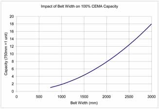
Figure 2—Impact of belt width on belt carrying capacity.
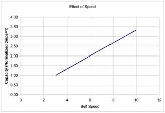
Figure 3—Impact of belt speed on belt carrying capacity.
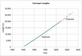
Figure 5—Growth of conveyor lengths in last 70 years.
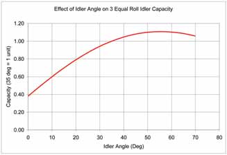
Figure 4—Effect of idler angle on conveyor capacity for a material with a 20°
surcharge angle.
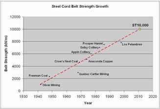
Figure 6—Growth of conveyor belt strength ratings in last 70 years.
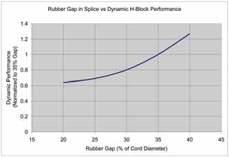
Figure 8—Dynamic performance versus cord to cord gap in a high tension splice
based on H-Block test data.
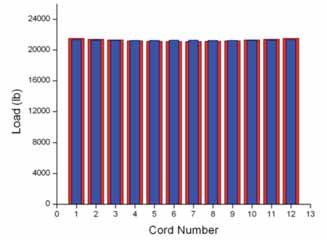
Figure 10—Cord loading in ST10,000 test splice.
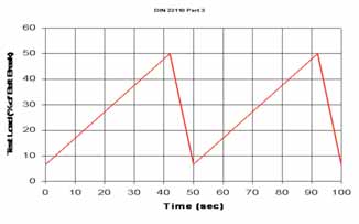
Figure 12—DIN 22110 Part 3 test load cycle (left).
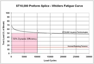
Figure 13—Two-Pulley Dynamic Splice Test results.
Capacity Controls
To meet an increasing production require-ment, belt capacities, belt lengths and belt
lift have seen steady increases. Belt capac-ity can be increased by:
1. Increasing belt widths,
2. Increasing belt speeds,
3. Using higher capacity idler geometry,
4. Employing low rolling resistance rubber;
and
5. Increasing belt strengths.
Figures 2, 3 and 4 illustrate the rela-tionship of each of parameters 1 to 3 on belt capacity.
Figure 2 shows the effect of increasing belt width on carrying capacity based a fixed speed and 100% CEMA capacity. 2 As a ref-erence, the chart uses a baseline of the first steel cord belt made in 1942 as one unit of capacity. From the chart it can be seen that the capacity for a 2,000-mm-wide belt is four times the capacity of a 1,000-mm-wide belt. That is, the capacity is a function of belt width squared. Currently, belts are com-monly made up to 3,200 mm wide.
When selecting wide belts with thick cover rubbers, belt weight becomes an impor-tant consideration. Belt handling weight lim-itations can reduce the possible roll lengths for such belts and may increase the number of splices required for long conveyors.
Belt capacity can be increased by increasing belt speed as indicated in Figure 3. This is a linear relationship. Over the past 30 years, average belt speeds have increased from less than 600 fpm (3 mps) to more than 800 fpm (4 mps) and higher. There are a number of belts running at 1,400 fpm (7 mps) and above. Higher belt speeds bring attendant requirements such as longer start and stop times, more elaborate drive controls, vibration and res-onance mitigation, and higher quality idlers with reduced total indicator run out (TIR) and balance requirements.
Figure 4 shows a simple analysis of the influence of idler angle on the carrying capacity of a belt on a conventional three roll idler for a material with a surcharge angle of 20° and a fixed speed. The sur-charge angle of a material is the natural angle at which the edge of the material makes to the horizontal on a moving belt. The analysis assumes equal roll lengths and 100% CEMA capacity.
At zero idler angle the capacity equates to a material with a surcharge angle of 20° piled on a flat moving belt. Although the optimum angle appears around 55°, idlers with this angle are seldom used as they would impose severe bending along the idler junctions of the belt which could cause premature failure of the rubber in that area. Most commonly used idler angles for three roll idlers are 35° and 45°. Other geometries with center roll lengths different to the wing roll lengths are possi-ble and are used. However, these are too numerous to detail here.
For a given installed motor power, low rolling resistance rubber (LRR) employed on the pulley cover of an overland conveyor belt can increase a belt’s capacity. Traditionally, a belt’s pulley cover rubber was the same as the top cover. However, studies and measurements of conveyor belt resistance to motion, 3,4,5,6 showed that rubber indentation was the major contribu-tor to belt tension for long, horizontal over-land conveyors. This led to the development of specialized low rolling resistant pulley cover rubbers that reduce energy losses from rubber indentation on idler rolls.
Currently there is well over 500 km of such low rolling resistance rubbers in serv-ice around the world. In addition to using less energy, one of the principal advan-tages of using low rolling resistance rubber is that it lowers the required belt tension for a given tonnage and installed motor power. Together with other energy efficient system components, this can account for as much as a 25% reduction in belt tension requirement.
For example, the longest single flight overland conveyor in the world (Curragh overland, Queensland, Australia 7 ) uses a ST1500 with low rolling resistance pulley cover rubber instead of a ST2500 using conventional pulley cover rubber. In anoth-er recent example, a 72-in. (1,829-mm) wide ST3500 overland conveyor belt, origi-nally installed with LRR rubber, was com-missioned with a capacity of 8,800 metric ton per hour (mt/h) copper ore. When the belt was replaced with a belt with non LRR pulley cover rubber, the conveyor motors could only support 7,000 mt/h capacity.
However, in the case of the ST10,000 where high elevation change is involved, the rolling resistance benefit is significant-ly reduced as the energy required to lift the material becomes dominant.
Conveyor lengths have also seen steady increases over the past 70 years, as shown in Figure 5. Belt lengths have increased from 670 m in 1942 at the Oliver Mining Co.’s Morris mine in the U.S. to 20,000 m in 2007 at the Wesfarmers Curragh over-land conveyor at the Curragh North mine, Queensland, Australia. However, conveyor lengths have not yet dictated maximum belt strength. The longest single flight con-veyor in the world employs a ST1500. Maximum belt strength is dictated by high lift slope or drift conveyors.
Belt lift and strengths show a similar trend. Over the past 70 years we have seen maximum belt strengths exhibit a steady, approximately linear increase, as shown in Figure 6. According to this chart, maxi-mum belt strength was forecast to reach 10,000 kN/m by the year 2011.

ST10,000 Development
To achieve a successful ST10,000 belt
design, certain requirements had to be
met. The quantity and strength of the steel
cords in the belt had to achieve at least 10,000 kN/m breaking strength. These
cords had to be designed to meet interna-tional standards of rubber penetration to
ensure good fatigue life, flexibility and field
performance. Due to the increasing de-mand to operate belts at lower safety fac-tors, the belt splice had to have a dynamic
efficiency (relative reference fatigue
strength) of at least 50% as defined in DIN
22110 Part 3.
Cords—Flexible steel cords that are suitable for conveyor belts have been developed over many years by a small num-ber of specialized companies. Typically, these steel cords are made from steel fila-ments coated with zinc. Zinc is used to provide catalytic protection of the steel in the event that the cord is accidentally exposed to moisture. The zinc is also used to provide excellent bonding to rubber.
Conveyor belt cords differ from many common steel cords in that they cannot have residual process oils on them, as this would compromise the rubber adhesion to the zinc. This is the primary reason why there are only a few manufacturers worldwide—none are located in the U.S. The cords are also designed in such a way to permit rubber to penetrate between the filaments as this helps to protect adjacent filaments from rubbing against one another and fretting which could cause premature failure. Specially developed high carbon steels are used to achieve high specific cord strengths with good dynamic fatigue properties.
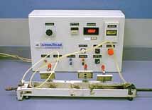
As rubber penetration has been found to be critical to successful performance of the steel cord in the conveyor belt, a special test has been developed to measure this. The test is incorporated in an international stan-dard, AS1333 Appendix L. Figure 7 shows a typical test apparatus. According to the stan-dard, a pressure differential of 100 kPa is established across a single cord in a 400-mm-long x full thickness sample cut from the belt and the pressure differential is mon-itored for 60 seconds. After 60 seconds the pressure differential is not permitted to change by more than 5.0 kPa in 60 seconds.
For the ST10,000, zinc coated, high carbon steel cords are used that meet the air penetration test described above.
Rubber—Conveyor belts typically use either two or three different types of rubber. The top cover rubber, the insulation rubber and the pulley cover (bottom cover) rubber. The top cover rubberis designed to pro-tect the cords from the transported materi-al. At the load point, where there is signif-icant relative motion between the belt and the material, the rubber must resist abra-sion wear. If the material is sharp and/or dense the rubber must resist cutting and gouging damage.
The insulation rubber is designed to provide bonding between the cords and the top and bottom cover rubbers. In the splice this rubber transfers the full tension load from the belt on one side of the splice to the belt on the other side of the splice. The quality of this rubber is a major contributor to the dynamic performance of the splice. The dynamic performance of insulation rubber is measured with laboratory tests. Some tests, e.g. AS1333 Appendix K, are performed on a small sample cut out of the belt and others, which also measure splice workmanship, are conducted on a full-length splice (DIN 22110 Part 3).
The small sample laboratory test is described in AS1333 Appendix K. According to the standard, the test is con-ducted on a belt sample containing five cords. The cords are cut on either end of a 100-mm-long block in such a way that the center cord extends from one end of the block and the remaining cords from the other end. The cords are gripped in the jaws of a test machine and a cyclic dynam-ic load is applied to them. The cyclic load is applied with a frequency of between 5 and 10 seconds. The minimum and maxi-mum loads applied to the cords are 3.6% and 36% of the nominal cord pullout load, respectively. The standard specifies that the center cord must not show signs of pulling out after 10,000 load cycles. For the ST10,000 belt, the insulation rubber exceeds 100,000 cycles on this test.
The bottom cover rubberhas little or no contact with the transported material as its primary function is to ride against the supporting idler rolls. As mentioned above, in certain applications the use of LRR pulley cover rubber can significantly improve a conveyor belt’s capacity.
Splice—In addition to the belt cord and rubbers, the primary consideration for the belt design is its dynamic splice efficiency. The efficiency of the splice is most important as the splice is required to transmit the total belt load from the cords on one end of the splice to the other. Dynamic splice efficiency is meas-ured with a large scale laboratory test. The test is defined in DIN 22110 Part 3 as the maximum test load that will just achieve 10,000 load cycles. The standard was the result of much research and test-ing at Hannover University in Germany 9 and others. 9.
Splice Design
As a steel cord’s belt strength increases so
does the number and/or diameter of steel
cords used in the belt. For a fixed belt
width, as the number of cords and/or the
diameter of cords are increased, the rubber
gap between the cords decreases.
In the splice, the cords from one end of the belt are laid between the cords from the other end of the belt. The cords from opposite ends of the belt must have a cer-tain minimum thickness of rubber between them in order to transmit the load from one cord to another without the rubber failing. From laboratory studies, typically the min-imum rubber thickness between cords is 2 mm to prevent a rapid failure. In practice, larger rubber gaps between adjacent opposing cords reduces the shear stress in the rubber which increases the fatigue life of the rubber and the life of the splice.
Figure 8 shows how dynamic perform-ance changes with cord to cord rubber gap based on 5-cord H-block test data. Traditionally, a minimum cord to cord gap of 35% of the cord diameter has been used as a design parameter for steel cord belt splices. This is used as the base perform-ance level in Figure 8. In the case of the ST10,000 splice, cord to cord gaps less than 35% are used but the gap is main-tained above 2 mm.
For high-strength belts, many large-diameter steel cords are required. In this case, in order to achieve sufficient rubber between adjacent opposing cords in the splice it is necessary to cut some cords short and organize the cords into an inter-weaving pattern. The higher the belt strength, the more cords need to be cut. When cords are cut some cords are short and extend only a little way into the splice and some cords are long and extend the full length of the splice.
To determine the best pattern in which to cut the cords it is necessary to calculate the rubber shear stresses for each of the possible patterns and select the pattern with: (a) the lowest rubber stress; and (b) the most uniform cord load distribution. This is best done using specially developed finite element analysis (FEA) where rubber and steel properties can be entered. Special consideration has to be included for the rubber physical properties as, unlike steel, rubber behavior is nonlinear and the nonlinearity must be defined in the model for each rubber used.
The rubber shear stress between cords in the splice not only varies with the rub-ber gap between cords but also with its longitudinal position within the splice and with the positions and directional sense of the adjacent cords. Figure 9 shows a sec-tion of the FEA analysis used in the devel-opment of the ST10,000. The black lines represent the cords. The colored section represents the rubber. The colored scale indicates the shear stress level in the rub-ber. Blue indicates the highest level of shear stress in the clockwise direction and red the highest level of shear stress in the anticlockwise direction. Green is zero shear stress. Based on many dynamic splice tests, a maximum shear stress of 2.2 MPa is targeted.
Figure 10 shows the FEA calculated load distribution of individual cords in the ST10,000 splice test loop. The red columns represent the cord loading of the individual cords entering from one end of the splice and the blue columns represent the cord loadings for the corresponding cords entering from the other end of the splice. The chart shows that the splice pattern achieves a very uniform load dis-tribution which is a primary goal for any splice design.
Splice Validation
To validate the dynamic performance of
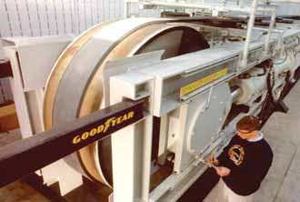
the ST10,000 splice, the splice was test-ed on the Two-Pulley Dynamic Splice
Tester in Marysville, Ohio at Veyance Tech-nologies Conveyor Belt Technical Center
(See Figure 11).
In the two-pulley dynamic splice test, the maximum test load is cycled every 50 seconds according to DIN 22110 Part 3. The load is applied in a saw tooth manner as shown in Figure 12. The cycle is designed to roughly simulate the tension load applied to the belt in the field. That is, the load is slowly increased at the beginning of the cycle, simulating load build-up from the tail to the head, then drops quickly, simulating the tension drop on the drive pulley.
Other test parameters used for the ST10,000 on this test are:
• 30.0-m-long loop x 279-mm-wide loop
• 50-second load cycle (42 up, 8 down)
• Cyclic load 6.6% to 40–60% of belt break
• Target life is 10,000 load cycles (5.8 days)
Per DIN 22110 Part 3, test results are shown in the form of a Wöhlers Curve in Figure 13.
Per DIN 22110 Part 3, the relative ref-erence splice fatigue strength (often referred to as the dynamic splice strength) is defined as the load at which the splice would achieve 10,000 load cycles on the test. In the case of the ST10,000, the splice exceeds 50% at 10,000 load cycles.
Successful dynamic performance of high-tension splices depends on good cord alignment and uniform spacing in addition to high performing insulation rubber. In order to consistently achieve good cord alignment and spacing, the ST10,000 splice employs Splice Preforms. Essentially, these are pre-molded rubber panels with ready-made grooves at the cor-rect cord pitch. The wide panels maintain cord straightness due to their high lateral bending stiffness. Preforms effectively eliminate the difficulties associated with cord alignment and spacing commonly experienced by splicers using conventional methods. In the conventional method, long, thin rectangular rubber noodles are used between cords. For large diameter cords (>10 mm) five noodles are used to fill in the triangular voids formed between the circle of the cord and the square formed around it by the rectangular noodles.
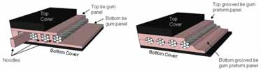
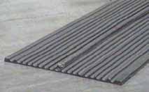
Figure 14 illustrates and compares the assembly of a conventional splice using rubber noodles (left) and one using splice Preforms (right). Figure 15 shows a rubber splice Preforms.
Good cord straightness and spacing uniformity provide measurable perform-ance benefits. In a static break test con-ducted by an independent laboratory in South Africa a 1,200-mm ST1250 Pre-form splice exceeded the nominal break strength of the belt. This was 10% better than the best conventional splice made on the same belt. Similarly, on two-pulley dynamic splice tests conducted on a ST4500 splice on Veyance’s Two-pulley Dynamic Splice Test, Figure 11, dynamic splice life of a splice made with Preforms was increased by 30% compared with a conventionally-made splice using noodles.
Benefits and Challenges of the ST10,000
The ST10,000 offers a number of benefits.
The primary one, as discussed above, is its
application to high-lift conveyors. To put
this in perspective, let’s look at how it
could be applied to an existing well-known
application.
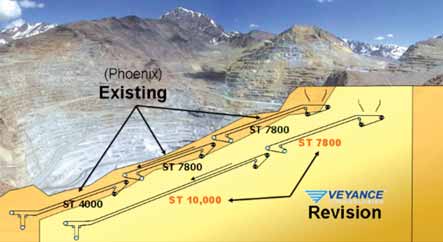
Currently, one of the highest-rated con-veyor belt operations is at Los Pelambres copper mine in Chile. This downhill sys-tem uses three conveyors with two ST7800 and one ST4000 belt to com-plete the drop from the mine to the coast. Using an ST10,000, the same drop can be achieved with only two conveyors—one ST10,000 and one ST7800, as shown in Figure 16. This arrangement eliminates one transfer station. In doing so, it reduces the risk associated with every additional component required for a trans-fer station. It reduces belt wear, the poten-tial for belt damage, and the need for maintenance manpower for the transfer station. In this particular application, where much of the belt operates inside tunnels, maintenance access is difficult for interim transfer points.
Potentially, an ST10,000 would be capable of a 40-km single flight although economics may favor a lower strength belt and booster drives.
Although the development of the ST10,000 is a natural step in the advance-ment of conveyor belts, it brings challenges to other conveyor components. For exam-ple, the tremendous torque required to drive an ST10,000 exceeds current gearbox technology. Fortunately, electric motor manufacturers’ have anticipated this devel-opment and have designed gearless motors to work with an ST10,000 belt. The gear-less motor development is based on proven, existing technology that has successfully been in use for cranes for several years.
Operating Tensions
The operating tension of any conveyor belt
depends on the safety factor chosen for its
application. For each application the cho-sen safety factor is a risk decision that
depends on many factors. Higher safety fac-tors increase splice and cord fatigue life and
increase the margin of safety that can
accommodate accidental damage. Lower
safety factors reduce splice life, cord fatigue
life and the margin of safety following acci-dental damage. If a belt is a lifeline belt, a
belt failure would stop mine production
until such time as the belt is repaired or
replaced. In large mines, this can amount to
millions of dollars lost production per day.
Practical experience suggests that seri-ous belt issues most commonly occur after the belt has been weakened by accidental damage that is not repaired quickly. In practice, high lift high tension conveyor belts have commonly been designed to run around safety factors of 6:1. Examples are the ST7800 belts at Los Pelambres (8,500 kN/m actual break, 1420 kN/m operating) and the Prosper Haniel ST7500 (8,200 kN/m actual break, 1370 kN/m operating). The ST6400 Drummond Coal slope belt in Alabama, operates at 5.7:1 safety factor (6,400 kN/m actual break, 1,120 kN/m operating). These belts have all exceeded 10 years service life.
The appropriate safety factor for a given application should be determined from a risk analysis that would include considera-tions of how critical the belt is to the oper-ation, the probability of belt damage from impact and/or tramp material, how good the belt maintenance will be, the impact of the stopping and starting dynamics, the effect of the transitions and vertical curves on belt tensions and the likelihood of the belt’s capacity being increased in the future.
Beyond increasing the basic breaking strength of the belt, a belt’s capacity to operate at low safety factors can be enhanced by increasing the dynamic splice efficiency, by taking measures to avoid accidental damage from high impact or tramp material and by constantly monitor-ing the belt’s condition to identify cord damage before it deteriorates into a catastrophic event.
Measures that can be taken to avoid impact damage and/or tramp material damage include careful chute design that reduces material impact on the belt and the use of an electromagnet before or after the chute to remove tramp metal objects.
Measures that can be taken to con-stantly monitor the condition of the belt’s cords exist in the form of rapidly develop-ing cord scanning technology.
Cord Monitoring Systems
Cord scanning systems have been around
for many years. Originally developed in
Australia, the technology has developed
rapidly in the past few years as it has been
integrated with imaging software. What
used to be a few lines on a graph indicat-ing the cord’s magnetic strength signal
which required specialist knowledge to
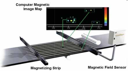
interpret is now a 2-D colored map of the
entire belt that is intuitively understood by
the user. The new software, which is avail-able real-time on a website, automatically
analyzes and interprets the data, prioritizes
damage sites for repair, emails alarms to
critical mine personnel and issues a com-plete report on demand.
Recent enhancements of this technolo-gy include embedded panels in the belt which, when cut through by an object that has penetrated the belt, will identify if the belt has been accidentally ripped. In this event, the software identifies the change in the magnetic image of the panel and will automatically shut the belt down before the entire belt is slit.
References
1
Wikipedia.org: “World Copper Production.”
2
CEMA Handbook, “Belt Conveyors for
Bulk Materials” 6th
edition, Conveyor
Equipment Manufacturer’s Assoc., USA.
3
Hager & Hintz “The Energy-Saving
Design of Belts for Long Conveyor
Systems” Bulk Solids Handling, Vol.
13, No. 4, November 1993.
4
L. K. Nordell, “The Power of Rubber,”
Bulk Solids Handling, Vol. 16, No. 3,
July/Sept 1996.
5
C. Wheeler, “Design considerations
for belt conveyors,” Australian Bulk
Handling Review, May/June 2007.
6
G. Lodewijks (1995) “The Rolling
resistance of Conveyor Belts,” Bulk
Solids HandlingVol. 15, pp 15-22.
7
Steven, R. (2008), “Belting the World’s
Longest Single Flight Conveyor,” Bulk
Solids Handling.
8
M. Hager and H. von der Wroge,
“Design of Steel Cord Conveyor Belt
Splices,” Bulk Solids Handling, Vol.
11, No. 4, November 1991.
9
L. K. Nordell, X. Qui and V. Sethi, “Belt
Conveyor Steel Cord Splice Analysis,”
Bulk Solids Handling, Vol. 11, No. 4,
November 1991.
Dr. Robin Steven is principal engineer at Veyance Technologies, Inc., Marysville, Ohio, USA.