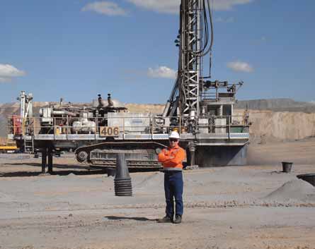
Anglo Coal's Drayton mine retrofitted the Sandvik CMS to this DR460 blasthole drill and has seen
considerable improvement in its drilling program. Foreground: Sandvik's Grant Field.
New System Manages Main Compressor on Rotary Drills
Several advancements allow dramatic savings in fuel and extend the service intervals for the engine and compressor
By Steve Fiscor, Editor-in-Chief
It sounds odd, but an idling blasthole drill is really nothing more than a high horsepower lube pump. The drill's main compressor is directly coupled to the engine. When the engine is running, the compressor is turning, burning fuel and generating heat. If the compressor is turning, it needs to be lubricated. Otherwise, the bearings would seize.
The idea always seemed a bit risky, but engineers love a challenge and several have considered changing the drill's compressor arrangement. For others, fiddling with the compressor was simply taboo. Early attempts to disengage the compressor from the drill relied on a clutching arrangement and met with varying degrees of success. The torque required to turn the compressor was so great the clutches were expensive to maintain and often rendered unreliable. Meanwhile, the OEMs building drills had to balance the compressors, which came from one source with a set of guidelines, with diesel engines from another source with differing set of recommendations.
Similarly inefficient, the bailing air on a mining class rotary drill was either fullon or nothing. There are times when a driller needs maximum air to bail a problem hole, but not all of the time. In fact, many readers might remember the big push during the 1990s to deliver as much air as possible to the bottom of the hole.
Today, engineers involved with large rotary drills have a new set of issues with which to contend. The diesel engines are smarter. They are recording duty cycles and tracking performance that could impact warranties. Modern diesel engines burn low-sulphur fuel and the price for fuel is getting more expensive. Meanwhile many of the principles related to compressors have remained the same. When the machine is not drilling, the compressor is a huge parasitic loss and the diesel engine is pointing it out through fuel burn rates.
Sandvik engineers had a hunch they could do a better job and started to develop a recently released compressor management system (CMS). The object was to reduce the fuel consumption and control the compressor a bit better. After a significant R&D investment, they discovered a breakthrough and determined how to disengage the compressor. In doing so, they found they could reduce the average torque on the drill's idling diesel engine from 58% to less than 7%. The first proof of concept testing for the CMS was performed on a DR460 at Sandvik's drill production facilities in Alachua, Florida, USA. Anglo Coal allowed Sandvik to perform prototype testing onsite at its Drayton mine in Australia. The CMS was fitted to the DR460 in May 2010. It has operated successfully for more than 7,000 hours.
Drilling productivity at Drayton improved. Mines using the CMS can expect to save money on fuel and extend the service intervals on the engine and main compressor, which increases uptime. The machines run much quieter than traditional drills and produce less dust. Because less air is forced through the hole, bit and drill string wear rates are reduced along with damage to the deck. The system is retrofittable and the payback is very quick.
Building Air Pressure
The purpose of the flushing air is to keep
the drilling face free. The air is injected
through the drill pipe to the bit. Is more
air always better? Grant Field, Automation
Product Line manager, Sandvik Mining &
Construction, doesn't believe so. He
explained that 40 psi at the bit is more
than enough. "If a drill is tooled up with
a 7-inch drill pipe, at full air it delivers 70 psi to the bit," Field said. "It just erodes
the bit and wears the drill pipe. The air is
coming out of the hole so fast that it just
becomes a big sand blaster." From industry-accepted standards, Sandvik knew the
appropriate velocity to bail the hole was
somewhere between 4,000 feet per
minute (fpm) and 8,000 fpm. The optimum operation, Field explained, would
use a low nominal flow for standard operating conditions, and then the extra
capacity would serve as insurance against
getting stuck in the hole.
Most of the time drillers have the maximum volume of air, no matter the drilling conditions. "The Sandvik DR460 for example comes equipped with a 2,000 cfm compressor," Field said. "The machine has a range of bit sizes and drill pipe. At its lowest extreme, the machine needs 1,000 cfm. With a 9-inch bit and 7-5/8-inch pipe, it has a 16,000-fpm uphole velocity—the cuttings are coming out of the hole at 300 km/hr." The point is not too much air, Field explained; there are times when the operator needs the air, but not full-on all of the time. When the machine is not drilling, the compressor is still maintaining that load.
In designing the CMS, efforts were directed at controlling pressure rather than volume. According to Field, building pressure in the compressor is what consumes horsepower on the drill. "If one calculates how much work goes into making pressure and how much goes into creating the volume of air, it's about 70:30; where 70% of the energy is used to build pressure," Field said. "Air pressure in the receiver tank pushes the oil through the system to lubricate the compressor bearings. There is no oil pump, or one could view the system as a very high horsepower oil pump."
On a good day, the drill operator cranks the engine, it starts and accelerates to a low idle. As the engine cranks, the compressor immediately starts building air pressure (and consuming horsepower). The compressor is fed through an inlet poppet valve. The problem is the poppet is a normally open valve. "Once the engine cranks and receiver has reached 7 psi, the load on the engine has already exceeded the power of the starter motors," Field said. "If the operator is unable to start the machine on the first try, he could be in big trouble. Batteries are depleted and he has to wait for pressure in the receiver to bleed down to atmosphere." With electronically controlled diesel engines, the mechanics can no longer boost the fuel for easier starting. From a warranty perspective, spraying ether into the air cleaner is no longer an option either.
Drills can be especially hard-starting in cold weather. Mine operators in the Andes know this first hand and see the engines gasping for air. "These drills were not originally designed to operate above 4,000 m, but that is where they now operate," Field said. During start-up, the CMS holds an inlet butterfly valve closed to allow the engine to crank, start and accelerate to low idle. "We can start the engine easily. It warms up at less than 10% load," Field said.
The actuator that opens and closes the butterfly valve is controlled electronically, eliminating the headaches associated with pneumatic valves, such as problems with freezing and corrosion. "Probably 30% of the maintenance associated with a drill has to deal with repairing the pneumatic regulation on the compressor system," Field said. "It's not the main compressor, it was all of the valves hanging off of it."
"One of the tests we did on the DR460 prototype was to measure the current it takes to crank the engine with an inlet poppet valve," Field said. "We found it was about 1,000 amps, or 500 amps per starter motor. With the CMS it's about 150 amps on one starter motor. The second starter motor is no longer needed. When all of the machines eventually incorporate CMS, we might be able to use one starter and one pair of batteries rather than two starter motors and four batteries."
Disengaging the Main Compressor In the offload state, when the engine is idling and the machine is not drilling a hole, the engine is using a lot of power to service the load. "We kept asking ourselves: How do we get the load off of the compressor?" Field said. "If we could isolate the compressor from the receiver tank, and suck all of the air and oil out of the main compressor so it has the same pressure on either side, the net load would be zero."
They then needed to test the system on a mining class drill. Theoretically, the technique should work. The downside, however, was the test could seize the main compressor—a $50,000 risk. It worked successfully on the first try. The key to making the concept survive was in the timing of the lubrication valves.
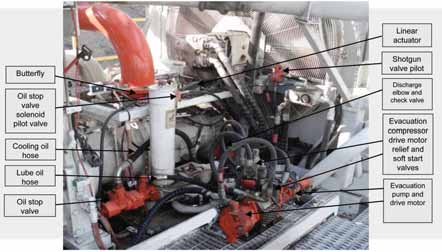
When the machine is not drilling, the CMS isolates the compressor from the receiver. "It cuts off the air inlet with a butterfly valve," Field said. "The evacuation pump is powered hydraulically. The unit we use is the same one Sandvik uses on its underground drills. We evacuate all of the air and oil out of the main compressor and we reduce load from 450 hp on the DR460 to 70 hp."
Throttling the Air PressureField formulated an idea based on the relationship between the vacuum in the compressor and the pressure in the outlet. He derived an algorithm that could calculate the volume of the compressor. When tested, they found that they could reliably calculate the volume of the compressor within 1%.
This was a major breakthrough. "Once we knew we could measure the volume of the compressor accurately, we could put that into an algorithm," Field said. "We could then develop a system that very accurately controls the butterfly valve on the compressor."
The CMS now knows the bit size, pipe size and the volume of the compressor. The driller tells the system the desired uphole velocity and using those four parameters it determines how much air is needed and throttles the compressor to deliver that much air.
There was another important variable the CMS did not understand, but the driller does, ground conditions. That system works well for normal conditions, but ground conditions often change. If the driller hits cracks, he needs the compressor to deliver more air. "We added bit air pressure to the algorithm," Field said. "From the bit air pressure, the CMS can determine whether it needs to throttle up or down to properly bail the hole."
The amount of bailing air is dependent on many factors. The drill operators need to decide what is appropriate for their conditions. "At the prototype testing site [Drayton], they wanted 12,000 fpm uphole velocity," Field said. "We knew they did not need that much and it was a psychological thing for the operators. The original PLC on the DR460 told them the uphole velocity and that was the accepted norm." Field set the CMS display at 12,000 fpm, but operated the drill at 8,000 fpm to see if the change would affect production. The drilling placebo worked and they proved it was simply operator's perception.
"One of the big advantages is that we are still storing air pressure in the receiver," Field said. "When the operator turns the air on, he instantly gets pressure. With a clutch arrangement, the compressor stops turning and pressure bleeds from the system. When the operator starts drilling he has to wait seven to 10 seconds for the system to rebuild pressure. That's the disadvantage with a clutch system, the latency."
"The brains behind the CMS is a PLC," Field said. "It's fully automated and it's continually optimizing without operator input. The system needs only to know bit size, pipe size, compressor volume max, and uphole velocity; everything else is automatic. When the system is running, it's infinitely adjustable. We set the minimum volume of the main compressor to 10% below the selected volume and it can go to maximum if it needs to. We need the minimum setting to maintain the pressure on the receiver and to hold oil pressure."
The system is based on closed-loop control. Because of the compressibility of air, compressors have a lot of latency, Field explained. "The loop control was very slow," Field said. "By the time the butterfly valve was set, and the system measured the change and reacted, it would over-shoot the mark. We developed the tap and test system. We bump the butterfly, wait for the system to stabilize and then measure the change, and if we need to, we bump it again. The actuator that moves the butterfly appears to be very jerky, but the system sees no oscillation at all."
"By intelligently placing the sensors, we also reduced the latency," Field said. "The vacuum sensor has been placed just below the butterfly. The receiver sensor has also been placed in a better position."
The CMS also has an anti-jamming feature. It monitors the bit air pressure and can tell if the hole is starting to block. "What we found at Drayton is that the operators prefer to have a bit of reserve," Field said. "We incorporated a feature called, 'Super Shot.' They can hit the Air On button for three seconds and they will get full compressor volume for 20 seconds to bail the hole and then it will automatically throttle back. They have not stuck a steel since and before CMS they used to lose a drill string at least once a month."
Shutting the System Down
Due to new diesel engine specifications,
the technique used to power the drill
down is just as important as the start-up
methodology. OEMs want to see the
engines shut down with less than 25%
load. "Prior to the CMS, the DR460 was
58% loaded when it was shut down,"
Field said. "The new diesel engines do not
like to be turned off when they are hot. It
damages turbochargers and injectors.
"With the CMS, we can unload the engine, dropping the exhaust gas down to 250ºC and 7% load," Field said.
Fuel Consumption and Engine Life
The CMS reduced fuel consumption by
33% on the Drayton drill. The average
engine load was reduced from 78% to
53%, which equates to 48 liters/hr in
fuel savings. Previously the mine had to
refuel the machine every shift (12 hours).
Now they can refuel it once per day. With
the extra 20 to 30 minutes, one to two
more holes could be drilled.
"When the DR460 was idling, it would normally burn 100 liters/hr. The CMS has now reduced that to 20 liters/hr," Field said. "The engine is basically only powering the hydraulics."
The CMS has also greatly extended service times and engine life. "We asked Drayton to service the compressor based on oil analysis rather than hours," Field said. "They had been changing the synthetic oil and filters every 500 hours at a cost of $8,000 for 400 liters. The average engine load has dropped by 50% and the engine oil is now lasting 1,000 hours with the CMS. The mine is fairly progressive with its oil analysis system. Same with the main compressor, they have not changed the compressor oil in 3,000 hours."
The DR460 at Drayton has a Cat C27 diesel engine. The mine was planning the mid-life PM at 6,000 hours. They are now at 11,000 hours and have just performed the mid-life PM. Cat has recommended extending the timing of the mid-life PM. "Cat will no longer give us figures for engine life," Field said. "That makes sense that an engine operating at 40% load will have a much longer life than one operating at 80%. Instead of hours, Cat now bases life figures on total fuel consumption."
The mines can fairly accurately calculate engine life using the CMS. As an example, a B-rated Cat C27 diesel engine, which is an engine running at more than 70% average load, will burn 1.2 million liters of fuel before it needs a rebuild. Reducing the load on the engine from a B- to a C-rating, which is loaded more than 50% on average, the fuel burn to rebuild can be increased to 1.6 million liters. If the drill burns fuel at a slower rate, the mine operators could see engine life double. Drayton is expecting to get 20,000 hours on its C27, Field explained, and they were originally expecting to replace the engine at 12,000 hours.
Training the Operators
Drill operators were first exposed to the
CMS during prototype testing at Drayton.
As far as the interface, the drill operator
sees two gauges on the display: receiver
air pressure and the flushing air pressure.
They would use these, particularly the
flushing air pressure, to determine
whether the hole is beginning to block
while drilling. Everything else is automatic. The display provides more information
at the bottom, volume of air, the position
of the butterfly, etc., but they are not
usually concerned with this information.

Training the operators on the new gauge took a special effort. "The drillers at Drayton were accustomed to seeing 70 psi flushing pressure," Field said. "When we implemented the CMS, the pressure dropped to 40 psi, which is where it should be, but they were so used to seeing it at 70 psi, they thought there was something wrong most of the time the drill was operating."
When the miners at Drayton were drilling at 70 psi and they saw the flushing pressure increase 5 psi or more, they thought they were blocking the hole. Now, the gauge is at 40 psi and, when it would increase 5 psi, they would immediately pull back on the feed, thinking they were blocking the hole. The CMS was actually throttling for the ground conditions. There were no problems, it was the way the system was supposed to work.
Pulling back on the feed was affecting the penetration rates. "With the new CMS implemented, they were 30% below the original penetration rates," Field said. "We told them not to worry about anything until the flushing pressure goes above 60 psi. We added a feature to make the gauge flash when it went above that limit. Penetration rates improved dramatically. Subsequently, they have broken the shift records six times. One crew recently drilled 1,238 m in a 12- hour shift."
Ground conditions vary at Drayton. One section of the mine is consistent and that's where the system was initially tested, before moving to a more challenging area with a diorite intrusion. "In that area, they go from 88 mPa [megaPascals] to diorite 450 mPa all in one hole. Then, directly below the diorite they have oxidized coal at 20 mPa," Field said. "The oxidized coal is so fine it flows like water. If the operator was not quick enough with full air, the oxidized coal would come up the hole and block at the collar. The CMS eliminated the plugging problems with the oxidized coal."
Other Fringe Benefits
Drayton is located fairly close to a residential area and they have to contend
with some constraints regarding dust and
noise. If far less air is moving though the
hole, dust emissions are lower. "The
water-injected dust suppression can now
keep up with the drilling," Field said.
"Previously, the drill overpowered the
dust suppression system. They can drill
now with little or no dust." The operators
have said they are no longer constantly
cleaning the windows or washing down
the deck. They have observed an increase
in average bit life. And, they are not
wearing down the deck. The chips are
coming out of the hole slowly and forming a more consistent pile of cuttings at
the collar.
The noise on a rotary drill by Australian standards is typically 118 decibels (dBa) with full air and the pipe down the hole about 5 m. With the CMS, the noise is has been lowered to 112 dBa.
The CMS can be retrofitted. Sandvik has to perform a machine audit, which allows the company to custom design the CMS for that particular machine. "We have tried to standardize the sub assembly," Field said. "About 80% of the kit is standard, the rest is the difference in hoses and wiring. We have tried to keep as many parts as possible standard."
The question Field answers most is: Why now? He explains there has been this cultural belief that the compressor was a mysterious device that should never be altered. "When we started to push the accepted boundaries, we started to discover that was simply untrue," Field said. "Certainly the electronic control of the new diesel engines was a motivating factor. No one had tracked the fuel burn on a drill."
Synthetic oils also played a big role. "We would have had more a lot more trouble evacuating the compressor with traditional oils," Field said. "The components would probably not have survived using Dexron II."
Sandvik did not change the drill. There is nothing unique about the engines or the compressors. It changed the peripheral system that regulates the compressor and, if the operator needs it, it delivers more air. The company expects to have a CMS system operating in a hardrock benching application in the Andes by June.