 Modern diesels require high fuel cleanliness to achieve maximum engine performance and component
life-cycle
expectations. Installation of proper filters, on the machine as well as on bulk fuel storage tanks
and transfer
equipment, can help obtain better fuel economy and extend fuel injector service life.
Component life, according to Simon
Bishop, a product support specialist with
Caterpillar Global Mining, is a function
of basic design, proper application, and
quality of maintenance and repair. A
major factor within “quality of mainte-
nance” is selection of the proper fluid(s)
required by a component, such as fuel,
oil, grease, coolant or hydraulic fluid—
and implementing the correct proce-
dures to ensure that these fluids aren’t
contaminated before, during or after
installation.
It’s estimated that equipment mainte-
nance and repair expenses account for
about one-third of overall haulage costs.
Taking it one step further, Caterpillar
reports that maintenance/repair costs
involving transmissions, hydraulics, final
drives/differentials and fuel injectors typ-
ically total up to 70% of overall machine
operating costs. And to top it off, some
studies show an estimated 75% of com-
ponent failures are the result of surface
degradation caused by fluid contamina-
tion. So, it’s simply good business to pay
attention to the fluids that keep major
components functioning as originally
designed.
Defining Dirt
How, exactly, is fluid contamination
defined? According to Bishop, it’s any-
thing found in a fluid that doesn’t belong
there. Contaminants generally fall within
two basic areas: particulates (dirt, met-
als and fibers), and other unwanted
ingredients such as water, air—even
heat. Although many of the latest oils,
greases and coolants are, for the most
part, high-tech products designed for
use in high-tech equipment, the process
of contamination often begins at a very
low-tech level that can involve every-
thing from whether and how well a vehi-
cle is washed before it enters the shop,
to what type of material the maintenance
crew uses to soak up accidental oil
spills. Contamination problems aren’t
always apparent to the naked eye; even
particulate contaminants that are con-
sidered large are still less than one-fifth
the thickness of a human hair, while
small particles are about one-third the
size of the big ones.
Fluid contamination control in all
phases of off-road equipment operation
is a concept that has rapidly gained trac-
tion in recent years, due in no small part
to new technologies, tighter regulations,
basic business economics and other fac-
tors that are forcing equipment owners
and operators to consider the expensive
consequences that can result from lax
fluid storage and handling practices. As
Caterpillar’s Bishop explained in a pres-
entation at the 2010 Cat Global Mining
Forum, inattention to contamination con-
trol can be disastrous to an operation’s
bottom line—and conversely, a well-
planned and executed CC program can
yield millions of dollars in reduced repair
and replacement costs over a haulage
fleet’s life cycle.
Citing a case history involving an
African open-pit mine, he noted that after
the operator implemented “world-class”
fluid cleanliness practices for the mine’s
fleet of Cat 785C haulers, component
life-cycle increases ranging from more than 28% for truck engines to almost
62% for wheel group assemblies were
achieved, wheel bearing life was extended
to 20,000 hours, and by eliminating one
rear powertrain replacement over the
course of a 785C’s life cycle, the mine
was able to save $90,000 per truck,
equating to a $3-million savings across
the fleet. In addition, the mine had to
replace only 16 fuel injectors in a fleet
comprising 24 machines with 20,000
hours—representing one injector replace-
ment every 35,562 operating hours.
Among the many factors that com-
prise a well-planned defense strategy
against premature parts wear, injector
longevity has grown to be an area of
major concern in recent years as new
engine technology puts these precision
components under increased duress.
According to Pall Corp., a global supplier
of fluid filtration and separation prod-
ucts, there are three types of engine fuel
injection system failures attributed to the
presence of particulate contamination:
• Mechanical failures from component
wear and blocking component
movement;
• Electrical failures (typically as injector
solenoid burnout) from silting around
the poppet valve stem, restricting
movement; and
• Performance failures from blocking of
injector nozzles and altering injector
spray patterns.
The Port Washington, New York-based
company notes that as diesel fuel injec-
tion technology has progressed, so has its
sensitivity to contamination. With new
technology such as Electronically Con-
trolled Unit Injectors (EUIs), injector
nozzle openings are 6–7 µm in diameter.
These openings can become blocked or
suffer erosion from particulate contami-
nation as diesel fuel is passed through
them at high pressures. Nozzle shape can
be changed or spray patterns altered,
adversely impacting engine performance
in the form of reduced power output and
poor fuel economy.
The High Pressure Common Rail
(HPCR) fuel injection technology used in
the latest off-road diesels offers improved
power and fuel efficiency and lower
exhaust emissions. To achieve these
results, however, HPCR systems operate
at pressures in excess of 2000 bar and
have injector nozzle openings in the 2–3
µm diameter range. This requires diesel
fuel 30 times cleaner than that which is
acceptable for standard EUIs and more
than 100 times cleaner than what is typ-
ically dispensed at the pump. According
to Pall, this level of cleanliness cannot be
achieved with onboard filtration alone;
supplementary bulk and point-of-fill fil-
tration is required.
The risk of fuel system problems also
increases with the use of ultra-low sulphur diesel fuels, which newer engines
are required to use. While it has been
reported the removal of sulphur has
shown no detrimental effects in engine
performance, the removal of other com-
pounds in the refining process can lower
the lubricity of fuel, resulting in potential
injector system component wear, espe-
cially with modern fuel technology such
as MEUI, HEUI and HPCR systems,
which are far more sensitive to inade-
quate lubrication from low lubricity fuels.
As previously mentioned, studies have
shown major component life-cycle costs
(calculated by determining cost to
rebuild a component divided by compo-
nent life in hours) represent the lion’s
share of total machine operating costs—
and engine costs alone represent about
40% of that share, followed closely by
final drive/differential, transmission/
torque converter and miscellaneous
costs. Given the potential damage con-
taminated fuel can cause in modern
diesels, plus the sheer volume of fuel
that large mines require for operation,
one of the largest payoffs from a contam-
ination control effort would likely origi-
nate from a mine’s fuel handling and
storage facilities. Proper bulk storage of
fluids—sometimes a forgotten link in the
chain of fluid cleanliness—can play a
huge role in combating contaminants.
Size Systems Carefully
As Pall Corp. points out in its technical
literature, funding for capital projects
such as fuel system upgrades can some-
times be difficult to justify. Even when an
upgrade has proven to be a necessity or
at least a viable proposition, cost is one
of the main defining attributes a mine
site looks at when making a purchasing
decision. The size of a filtration system is
one of the main contributors to this cost.
Diesel filtration systems are typically
sized using a formula that takes into
account the pump flow rate (or rate of
delivery required), fuel viscosity, fuel den-
sity, and system pressures. Once these
factors are known, a system can be sized.
However, according to Pall, in many
cases fuel filtration solutions that are
being presented to mine sites are drasti-
cally undersized for their intended pur-
poses. Why? Because these systems are
often missing one key aspect in the sizing
formula—the annual fuel quantity being
used at the mine site and the levels of
contamination that this fuel carries.
It’s not unusual for a mine to con-
sume more than 200 million liters of
diesel fuel per year, and some larger
mines may use more than 400 million
liters annually. When dealing with these
huge volumes, it’s important to under-
stand the amount of contamination that
the filtration system is expected to
remove. Pall’s experience indicates that
for a mine site with annual diesel fuel
consumption of 200 million liters a year,
with a delivered fuel cleanliness level of
ISO 21/19/16, the amount of contamina-
tion removed by a filtration system each
year can total as much as 1.6 tons.
Additionally, with a water contamination
level of 500 ppm, a coalescer system
would be expected to remove some
100,000 liters of water each year.
Using this fuel volume as an example,
it’s important to understand the actual
capacity of the filter elements typically
installed in mining bulk diesel systems.
Pall says it is common at mine sites to
see filter installations sized to handle
1,200 liters/min of diesel fuel; such a system may have dirt-holding capacities
as low at 900 grams for the three ele-
ments in the housing at the given flow
rates. Taking into account the 1.6 t of
annual contamination, this equates to an
annual consumption of 1,388 elements.
That rate of filter consumption, and
its attendant costs, might overshadow
any benefits from the installation at all.
Pall, which in addition to its filtra-
tion/separation product line offers fluid
analysis services and component cleanli-
ness auditing, thus emphasizes that
many factors including pump flow rates,
viscosity, density, temperature and pres-
sure must be considered in any formula
used to size a bulk filtration system—a
task best performed by an experienced
vendor.
Going Under Analysis
The care and cleanliness of engine lubri-
cating oil is another critical area that can
yield significant benefits from contami-
nation control measures coupled with an
oil analysis program. Oil analysis services
are available from many sources, and
recent developments in this technology
now allow thorough analysis at almost
real-time rates.
WearCheck, a company that special-
izes in oil analysis, emphasizes that the
effectiveness of any oil analysis program
is strongly affected by how well the main-
tenance staff understands the program
and by the quality of their input to the
testing service. An important fact to bear
in mind, according to the company, is
that oil analysis should not be viewed as
a replacement for normal maintenance
techniques. It is a first-stage monitoring
tool that identifies a problem; diagnostic
tools are then required to physically con-
firm the problem and isolate the defec-
tive component. Oil analysis comple-
ments diagnostic tools, it does not
replace them. When the information from
all testing sources is combined, the
result is a powerful management tool for
monitoring and controlling machine
health.
Oil analysis works on the principle of
detecting progressive wear by establishing
a baseline of normal wear metal and con-
taminant levels and trending the results
from subsequent samples. WearCheck
recommends implementing a set of basic
policies that can maximize the effective-
ness of any oil analysis program.
• Ensure total commitment from top man-
agement all the way down to the work-
shop floor.
• Make members of the maintenance
team aware that their efforts do make a
difference to the longevity of the
machines.
• Clearly define and communicate sam-
pling policy and frequency.
• Appoint and train responsible people to
take the samples and complete the
sample submission forms accurately.
• Appoint a competent senior mechanic
to carry out troubleshooting and ensure
all physical diagnostic tools are
available.
• Train a clerk to keep accurate records
of oil analysis and physical tests car-
ried out on components at service
intervals and during troubleshooting.
• Ensure feedback is returned so that
oil analysis records can be updated and
the information is available to the
diagnosticians.
Counting the Costs
It’s been estimated the actual costs of
basic contamination control and overall
systems cleanliness in an operation
often amount to less than 3% of poten-
tial total costs incurred due to fluid
contamination—not bad for an invest-
ment that has the potential capability
to reduce an operation’s maintenance
budget, increase fleet mechanical
availability by significant single- or
even double-digit percentage points,
and even improve employee morale and
accountability.
Take the First Step in Contamination Control: Delete Dirt and Debris
A contamination control program doesn’t have to be high-tech
to be effective—but it does have to include all areas of an oper-
ation that may contribute to fluid contamination problems.
Here are a few basic guidelines that can help achieve a higher
level of cleanliness:
 Contamination control starts with good basic housekeeping: shop-approach
aprons should be paved and kept free of dirt and debris. Interior floor surfaces
should be sealed and accidental fluid spills should be cleaned up with absorbent
pads or with a wet/dry vacuum. Avoid using granular absorbent materials that can
create airborne dust.
• Cleaning floors daily. Consider sealing floor surfaces.
• Keeping tools clean and organized.
• Keeping work benches clean and organized.
• Storing parts off the floor.
Use a vacuum or absorbent pads to clean up accidental
spills, and finish the cleanup with a powered floor scrubber, or
mop with degreaser. Avoid using granular absorbent materials
that can produce dust.
All hose and tube ends should be plugged or capped. Hoses
and tubes removed during a repair should be cleaned internal-
ly before being reinstalled. Keep parts/components packaged
until ready to install. Protect in-process parts when not being
worked on.
Consider using an oil-service preventive maintenance cart
containing:
• Vacuum pump and tubing
• Clean magnetic plugs/screens
• Sample bottles
• Filter cutting tool
• Digital camera
• Low-lint towels
• Latex gloves
• Resealable plastic bags
Filter all new fluids upon arrival and during transfer.
Seal fluid reservoirs and bulk tanks. Install high-quality des-
iccant and particulate filters on tanks. During refueling proce-
dures, clean fueling ports and nozzles before fueling and cover
them after fueling. Drain sediment and water from machine
tanks at PM intervals, as part of PM checklist.
|
On-site Fluid Analysis in Minutes, Not Days
It didn’t take a six-year federal study to
show that miners want fluid analysis equip-
ment on-site for speedy but comprehensive
results as part of their equipments’ preven-
tive maintenance programs. But that’s
what a 2004 U.S. Department of Energy
study concluded, and what an increasing
number of players in the mining industry,
including service provider Megatrol Inc.
and equipment provider P&H Mining
Equipment, are moving to implement.
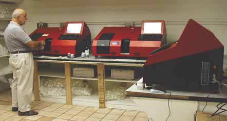 Claimed to be as easy to use as an ATM, more and more mine operations are using fluid diagnostic
equipment at
their sites such as these from On-Site Analysis Inc. These on-site analyzers provide
comprehensive results in 10
minutes or less showing metal wear, contamination and other factors.
Fluid analysis is vital to machine
health, but collecting and sending hun-
dreds of lubricant samples each month to
an off-site laboratory is costly at more
than $20 per sample. That cost is multi-
plied when mine managers have to wait
for results, anywhere from days to weeks.
Real-time on-site analysis is now elim-
inating the wait and reducing the cost. In
10 minutes or less operators can have
comprehensive analysis showing metal
wear and contamination before equipment
loss and downtime become catastrophic,
allowing mine managers to repair their
equipment faster and get it back in serv-
ice more cost effectively than ever.
Jon Rose, who has 40 years of experi-
ence in the mining industry as owner of
Megatrol Inc., a provider of proactive
solutions for efficient mining equipment
management and maintenance, said “An
extra hour of operation can lead to very
expensive downtime and that is a prime
reason for on-site oil analysis.”
For real-time analysis and repeatabili-
ty of data that can help maximize mining
equipment production uptime, Megatrol
turned to On-Site Analysis Inc. (OSA), a
global leader of used-fluids diagnostic
analysis technologies. OSA was formed to
address the market need for faster, com-
prehensive, laboratory quality testing and
consequently developed the MicroLab
on-site analyzer. Essentially a “lab in a
box,” the on-site analyzer was developed
to produce lab quality results in a small-
er package and with an easy to use touch
screen interface.
The analyzer can identify the pres-
ence of 20 metals, measure physical
properties such as glycol, TBN, soot
(diesel engines only), fuel dilution, water,
nitration, and oxidation, and also meas-
ure viscosity. It has an integrated particle
counter and provides comparisons
against expected equipment wear rate
curves similar to off-site labs, unlike
hand-held analyzers that are limited to
single tests like viscosity.
After analysis is complete, the equip-
ment delivers a diagnostic report that
includes suggested preventive steps. The
data can be downloaded to a password-pro-
tected Web site for review from anywhere
in the world. Results also are e-mailed as an
alert if an abnormal finding is discovered.
Megatrol is successfully using two
OSA labs at a mine in Gillette, Wyoming,
USA, testing 600 to 800 fluid samples
monthly from a fleet of several hundred
vehicles including trucks, dozers, scrap-
ers, and support equipment. According to
Rose, such fast test results from analysis
can save an engine, transmission or a
major bearing on key mine equipment.
“With timely on-site analysis and
repair, a high-volume mine site could
save thousands by avoiding unscheduled
repairs and downtime,” said Rose. “By
replacing a $5 hose in time, for instance,
you could save a $120,000 engine or
$70,000 transmission.”
Every minute of downtime is scruti-
nized and any unscheduled downtime
must be minimized, particularly on key
equipment that can adversely affect pro-
duction if that equipment breaks down,
said Barnes.
P&H has added on-site fluid analysis to
its Prevail Remote Health Monitoring
Program, which expedites equipment
diagnosis, maintenance, and repair
through its MinePro Services network, and
is starting to roll it out globally. The PRHM
program allows managers and technicians
to monitor all key equipment vitals online.
“Working with OSA, we’ve added on-
site oil and hydraulic fluid analysis, plus
an ability to track historic component
wear trends with flexible online reporting
to our ability to monitor vitals like tem-
perature and equipment fault logs,” said
Barnes. “This gives mine managers and
technicians near real-time ability to ana-
lyze, diagnose, predict, and respond to
needed repair from a one-stop, secure
website interface, or to receive critical
email alerts. It also allows mine opera-
tions to benchmark and develop trends
which lead to optimized performance and
best practices.”
According to Barnes, the availability of
more immediate results allows operators
to streamline preventive maintenance pro-
grams and optimize routine maintenance
tasks and oil change intervals. The
improvement to machine availability and
utilization alone can significantly improve
the operation’s bottom line and has the
additional benefit of reducing disposal
costs and environmental impact.
As a result, “mines could achieve ROI
in less than one year with the Prevail
Remote Health Monitoring Program,
including on-site fluid analysis,” said
Barnes.
|
There’s an App for That…
Filter supplier Luber-finer has released an “app” for
Android smartphones that provides one-click access to
filter product search and cross-reference information. It
can be downloaded without charge from the Luber-finer
Web site (www.luberfiner.com/app) or from the Android
Market. In addition to product information, the app
allows users to quickly look up the nearest Luber-finer
distributor or reseller. The app covers the entire range of
Luber-finer filters for off-road and on-road heavy-duty
markets, and allows users to conduct product searches
for the correct filter by nearly any make, model and year
with up-to-date specifications and data for all filter
applications. According to the company, apps for other
smartphone platforms are in development and will be
available soon. |
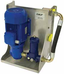
Oil Conditioning, on the Spot
SKF recently introduced a stationary Oil
Conditioning Unit that claims to enhance
lubrication performance by serving as a
low-pressure pump filtration unit that cir-
culates the oil in a system. The OCU
removes contaminants from the oil supply
and can maintain a desired temperature
range throughout the conditioning
process. It is designed to connect direct-
ly to sumps, bearing housings, gearboxes,
compressors and other machines, and is
available in two versions (filtration only or
filtration with an air or water cooler to
lower the oil temperature). Both remove
dirty oil from the bottom of the oil reser-
voir and return filtered oil to the top of
the reservoir. Units can perform continuously without constant maintenance (only
periodic filter changes are required). According to SKF, benefits of the conditioning
process include optimized lubrication conditions with correct oil viscosity, reduced
component wear, extended component and lubricant service life, reduced mainte-
nance and repairs, reduced oil consumption and disposal costs, and improved
machine reliability and productivity. |
Fighting Fluid Contamination in Flood-Damaged Equipment
Widespread recent flooding in Queensland and other
Southern Hemisphere regions has left many communities
devastated and caused serious disruptions to industrial activ-
ities such as mining.
In Australia, for example, flooding has affected the
Queensland coal industry, not only causing producers to lose
an estimated billion dollars in lost production, but also cost-
ing them many hundreds of millions to repair machinery and
infrastructure inundated by water.
Dingo Maintenance Systems, a supplier of mine-mainte-
nance software solutions based on CBM and oil analysis prin-
ciples, recently issued a technical bulletin outlining the
types of damage to look for and the maintenance response
needed to cope with water-damaged equipment.
According to the Dingo bulletin:
• Equipment that may have been fully submerged will require
a full recovery effort, including a flush of all systems: Make
sure provisions are in place to document and track con-
ditions of each asset/component for any potential warranty/
insurance payable issues, as well as to accurately monitor
conditions going forward.
• Do a thorough examination of bulk oil storage facilities: If
contaminated, oil should be removed, tanks flushed and
corrective actions taken. Do not place new oils into an
already contaminated source. Ensure that cleanliness of
newly arriving bulk oil is at acceptable levels as flooding
may also have affected vendors as well. Do visual checks
of oil condition and perform onsite testing if possible.
Sample all oils and fuels and expedite samples to your
testing labs.
• Establish a Mission Criticality and Priority List of which
equipment must be addressed first: This may require that
all engines have oil/filter changes once bulk oil supplies are
determined to be usable. Ensure that oil samples are taken
after drain so necessary condition monitoring can move for-
ward. Other component oils may be able to wait until a later
date; this should be a case by case basis. Closely monitor
the results of the next series of oil samples as there can be
residual contamination.
• Ensure that the warehouse facility has adequate inventory
of filters and breathers: Using contaminated, old or improp-
er inventory can be just as destructive as not doing any-
thing at all.
• Visually asses each location affected to determine specific
issues and steps for corrective actions. All affected sites
should understand that conducting a proper assessment
will, to a large degree, determine the time frame in which
sites can be back to full operation and production.
• Maintain clean work shop facilities: Ensure that additional
contamination does not result from muddy work environ-
ments. Wash equipment thoroughly,if possible, to facilitate
inspection and leak identification.
• Be vigilant in OEM oil/filter change intervals: Depending on
asset/mission criticality, consider falling back to one-half
normal intervals until conditions determine otherwise. This
is also important for kidney loop filtration on components
which were previously serviced in this way and not solely on
a condition-based schedule.
• Aggressively monitor fuel sources, as water, algae and
assorted microbials will be present: These conditions will
plug filters both in delivery applications and in-service
equipment. Biological growth bacteria, fungi or mold is
likely due to the presence of water in the fuel. For locations
that use biodiesel, this fuel has a typical shelf life of
around six months—but that can be reduced by many
factors/variables.
• The effects of water contamination can be wide-ranging,
including:
• Shorter component life due to rust and corrosion: Water
attacks iron and steel surfaces to produce iron oxides.
Water teams up with acid in the oil and will corrode fer-
rous and nonferrous metals alike. Rust particles are abra-
sive and get ground up in the system where the associat-
ed metallurgical wear elements can serve as a catalyst that
increases the process at an exponential rate. Abrasion
exposes fresh metal which corrodes more easily in the pre-
sence of even lower concentrations of water and acid.
• Water etching/erosion and vaporous cavitation: Water
etching can occur on bearing surfaces and raceways, pri-
marily caused by generation of hydrogen sulphide and
sulphuric acid from water-induced lubricant degradation
with vaporous cavitation.
If the vapor pressure of water is reached in the low-
pressure regions of a machine, such as the suction line
of a pump or the pre-load region of a journal bearing, the
vapor bubbles expand. Should the vapor bubbles be sub-
sequently exposed to sudden high pressure, such as in a
pump or the load zone of a journal bearing, the water
vapor bubbles quickly implode and simultaneously con-
dense back to the liquid phase. The water droplet im-
pacts a small area of the machines surface with signifi-
cant force in the form of a needle-like micro-jet, which
causes localized surface fatigue and erosion.
Water contamination also increases oil’s ability to en-
train air, thus increasing gaseous cavitation.
• Hydrogen embrittlement: Hydrogen embrittlement occurs
when water invades microscopic cracks in metal sur-
faces. Under extreme pressure, water decomposes into
its components and releases hydrogen. This explosive
force causes the cracks to become wider and deeper,
leading to spalling.
• Oxidation of bearing babbitt material
• Wear caused by loss of oil film or hard water deposits: Rolling element bearings and the pitch line of a gear
tooth are protected because oil viscosity increases as
pressure increases. Water does not possess this property.
Its viscosity remains constant (or drops slightly) as pres
sure increases. As a result, water contamination increas-
es the likelihood of contact fatigue (spalling failure).
• Be aware of the effects of water on lubricating oil:
• Accelerates oxidation of the oil
• Depletes oxidation inhibitors and demulsifiers
• May cause some additives to precipitate
• Causes ZDDP antiwear additive to destabilize over
180°F
• Competes with polar additives for metal surfaces. |
As featured in Womp 2011 Vol 01 - www.womp-int.com