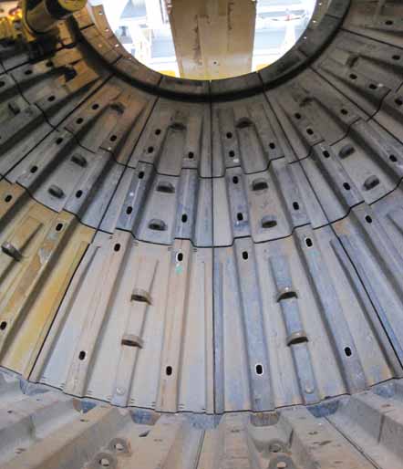
Steel liners installed at the feed head of a grinding mill. (Photo courtesy of ME Elecmetal)
Liners for the Grinders
Liners do much more than just protect a mill’s shell, with current research aimed at
optimizing liner design and cutting milling costs
By Simon Walker, European Editor
A fascinating insight into historical practice appeared in a paper presented to the Chemical, Metallurgical & Mining Society of South Africa in 1907. The author, Ralph Stokes, described the liners then in use at the Waihi gold mines in New Zealand, where the ore was broken first by stamp mills, with subsequent grinding using tube mills. The hardness of the ore, Stokes explained in his paper, took its toll on the mill liners, the mills themselves being charged with 5½ tons of flints as the grinding medium.
As supplied two years earlier, the mills were designed to be lined using trimmed rectangular silex or stone blocks. However, the mine had had problems in sourcing suitable materials locally, and H. P. Barry, the operation’s general superintendent, had invented a replacement system that allowed the use of irregular rock fragments.
The home-built liners consisted of castiron frames, 18½ in. high, 15½ in. wide and 3½ in. deep, divided into four or six compartments into which quartzite pieces could be bedded using a cement-based mortar reinforced with flint fragments from the mills. Among the advantages of this system was the speed with which individual sections could be replaced when they were worn out or if a section fell out during operation. However, the cost of liners was significant, Stokes said, citing running costs of the mills at 1s 2d per ton of sand, with flints and liners accounting for half of this. The remainder was presumably accounted for by the energy input to turn the mill. Purely for interest, that milling cost converts to the equivalent of US$7.20 per ton in May 2010 dollars.
Fast forward to the present, and in a paper presented at the Comminution ‘10 conference in Cape Town in April, Johan Dahner and Alfred van den Bosch from Magotteaux reported on their perceptions of the split between energy, grinding media and liners in both primary and secondary ballmilling operations. Where an optimized liner design is used, they said, media account for over 57% of the total milling cost, energy 25.5% and the liner around 17% in primary milling. For secondary milling, the relative proportions are 59%, 33% and 8% respectively, although in neither case were actual milling costs specified.
What is clear, however, is that while the proportion of total costs incurred by energy use has fallen over the past 100 years, and media costs have increased in relative terms, liners still make up a significant cost item. What is more, Dahner and van den Bosch noted, a mill that has been fitted with an inappropriate liner can cost considerably more to operate than a comparable unit with a liner that has been optimized for the specific duty required, taking the type of ore, tonnage, mill geometry and other factors into account.
In addition, liner segments help remove pulp from the discharge end of the mill, here acting more as a pump for the slurry than as a lifting mechanism for the millbody contents, comprising rock and grinding media. The difference between a mill designed to operate in overflow mode or with a grate and pulp lifters is also important in this context, since the duty imposed on the liner is not the same.
While the physical characteristics of the ore being ground, such as its abrasiveness and the distribution of mineral within the rock, have a major influence on the choice of liner material, other factors also come into play. For instance, the rotational speed of the mill, and hence the relationship between gravity and the centrifugal forces acting on the rock particles and the grinding media, has a significant effect. The charge within a mill being run at 90% of its critical rotational speed will behave differently from that in one running at 75%, in which gravity has a greater influence. The trajectories of media and rock particles will be different, as will be the potential for grinding balls to impact directly on to the liner rather than the pulp, so what might have been a suitable selection for liner material under one set of conditions may well be inappropriate if operating conditions change.
Liner Materials: The Choices
In their contributed section on liner selection
and design in the SME’s 2006 publication,
Advances in Comminution, Professor
Malcolm Powell and his co-authors
provided a succinct resumé of current
material options for mill-liner components.
The choice, they noted, is principally
between various iron and steel alloys, and
elastomer liners that are based on both
natural and synthetic rubbers.
They noted austenitic manganese steel and chrome-moly steels have been materials of choice for SAG- and ball-mill liners, although the trend has been toward the use of higher-carbon chrome-moly steels for SAG mills. Where ball mills are concerned, the most durable alloys are now highchrome irons and chrome-moly white irons, both of which exhibit better abrasion resistance than any other liner materials yet developed.
“One interesting development, is the bi-metallic liner using a white-iron insert that can give increased wear-life in lowimpact abrasion-prone locations such as end liners. In addition, metal-faced rubber ‘Poly-met’-type products, with designs resistant to damage through ball impacts, are growing in application in SAG mills,” he said.
This interest in rubber-based liners for SAG milling flies in the face of the previous belief that a SAG mill, using large-diameter grinding media, was just too tough an environment for rubber. Indeed, while that remains true in the majority of situations— “big balls kill rubber liners,” said one industry expert interviewed by E&MJ—the combination of metal’s resistance to abrasion with rubber’s resilience to shock loading has opened new avenues for liner technology in some circumstances.
Rubber Developments
Expanding on this theme, the director of
Polycorp Ltd.’s mining division, Pramod Kumar, said there have been some significant
improvements made to both the quality
of rubber available and the design of
liner segments. Headquartered in Canada,
Polycorp is the successor to B.F. Goodrich
in the country, and claims to have supplied
rubber-based liners to more than 300 mills
world-wide.
“The theory was that rubber was good for lining secondary mills, but not for primary milling applications,” he said. “Now, rubber liners are being used in SAG and AG mills up to 32 feet in diameter, with modifications such as steel facing. The big advance here is that using rubber enhances the mill throughput,” he added, while admitting that rubber may not be the universal panacea. Rod mills in particular are less suitable for rubber lining, especially in areas of the mill where the rod ends could tear into the surface.
Discussing the different compounds that are now available, Kumar pointed out that it is not necessarily the case that a harder compound is better for mill liners. “The main criterion is how the compound can handle the abrasiveness of the rock,” he said.
“Steel liners will keep wearing out, and they are heavy to move around and store. With rubber liners, you don’t need so much inventory, so companies can plan better. And, of course, the other big advantage is that rubber-lined mills make less noise than ones with steel liners,” he said.
Practice Trends Affect
Liner Requirements
E&MJ asked one of Australia’s experts in
SAG-mill liner technology, Dr. David
Royston, about recent trends in SAG
milling practice and how this has affected
the design of liners. “In recent years, the
trend to smaller top-size ore feed into SAG
mills has been matched by a trend toward
smaller but more balls in the SAG mill
charge. High ball-to-rock ratios and low
overall mill charge levels are now widely
used. These practices can result in periodic
loss of rock charge and ball-on-liner
damage,” said Royston.
“Good liner life in aggressive milling environments requires careful mill operation to maintain the mill rock charge and avoid ball-on-liner damage, as well as a robust mill-liner design.”
Royston went on to explain that large shell-lifter face angles, used to impact the ‘lifter ball’ into the toe of the charge, can maximize ball energy transfer to the charge and avoid damaging ball-on-liner impacts. Wider liner spacing (say 44 rows in a 33-ft mill) can reduce ‘packing’ and increase the lifting rate, especially with smaller feed sizes, he added. The feed-head outer liner life can be extended by increasing the size of the plate bar that sits between the lifters.
Royston also noted new grates can slow milling rates: some mills change every second grate at relines, while others use alternating high and low grate-lifter bars, to maintain milling performance. The backflow of non-discharged rocks can limit the pulp-lifting performance and add to wear at the base of the pulp lifters. Adequate frontto- back depth in pulp lifters is necessary to ensure good pulp-lifting performance, with some SAG-mill operators having adopted curved pulp lifters, especially of the ‘hockey stick’ shape. These help the pulp discharge, especially of larger pebbles, and substantially reduce any backflow.
The issue of whether to use grates or an overflow system of pulp discharge is not, however, confined to SAG milling. Alfred van den Bosch of the Belgian-based wearparts specialist, Magotteaux, provided E&MJ with a rundown of work that the company has been undertaking in this area, with specific interest in milling practice in South Africa’s gold industry.
According to van den Bosch, Magotteaux’s testwork has shown that—contrary to popular belief—there is little practical difference in performance between overflow and grate designs of secondary and regrind mills in this application, although this is not the case for SAG milling, where the primary criterion is throughput rather than the fineness of the grind.
In an effort to demonstrate to South African mill operators that overflow grinding practice can save costs by doing away with the need for grate parts and their replacement, Magotteaux has now designed an interchangeable outflow system. By simply undoing a few bolts, van den Bosch said, the mill outflow can be changed from one mode to the other, and back again if that proves more effective at any time. The company has also been working on the design of the lifters at the discharge end of the mill, with a new design that can operate under overflow, semi-overflow or grate conditions now under test in a pilot mill.
Take, for example, the 18-MW SAG mill that is now operating at Equinox Minerals’ Lumwana copper mine in Zambia. Commissioned in 2008, the 38- × 20-ft mill is the largest in Africa, with a design throughput of 20 million mt/y. At the time, the company reported that it contains 600 mt of liners, with the heaviest individual section weighing 2.2 mt, while a reline takes about four days to complete at a cost of $1.5 million.
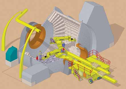
Clearly, manipulating a liner section weighing more than 2 mt is beyond the capabilities of manual handling within the awkward, yet confined mill interior. In consequence, Equinox has turned to Russell Mineral Equipment (RME), the Australian company that claims an approximate 80% share of the world market for mill relining machines, with units sold to over 160 mines in more than 40 countries.
With downtime a critical factor, especially where a mine relies on a single large mill for its primary grinding, the focus is often on keeping a reline as short as possible. According to RME, its top-of-the-range liner handler, a twin eight-axis relining machine, has cut the time needed by around three-quarters for large mills, representing a major cost saving.
The company’s product range extends from its Millmast system, which is designed for use in smaller mills and can handle liner segments up to 400 kg in weight, to the twin eight-axis machine, capable of manipulating segments of up to 10 mt. The ability to maneuver liner parts of this size safely and accurately has had a knock-on effect in terms of overall liner design, since fewer, larger segments are now needed.
Speaking at an export award ceremony in 2008, RME’s Managing Director John Russell said its mill-relining system has removed any constraint to liner size. “RME’s Thunderbolt recoilless hammers can knock out any liner remnant, and a mill-relining machine can place any size liner to millimeter precision, necessary for easy liner bolt placement. A 5 ton liner places as quickly as a 1 ton liner, and replaces the additional four liner placement maneuvers,” he said, emphasizing the benefits of now being able to use larger individual liner segments.
The Foundry Manufacturers’
Viewpoint
Eric Herbst, international sales manager
for the U.S.-based liner manufacturer, ME
Elecmetal said from the liner supplier’s
point of view, there is an emphasis on continuing
to develop processes, alloys,
designs and wear tracking. In particular, he
added, alloy development is an ongoing
part of the company’s business, and one of
its main R&D focuses.
“Most of our customers are extremely interested in testing new alloys in their mills, because by the time we are ready to test an alloy, there is a very good chance that our customers will benefit,” said Herbst. For example, we have recently developed a new alloy for high impact applications such as SAG mills that has increased our customers’ liner life by up to 20% compared to the alloys that are currently being used in those applications.
“We continue to regularly optimize our customers’ liner designs. This is an iterative process where we make incremental improvements to the liner design over time. A regular presence on site during shutdowns is extremely important part of this process.”
Herbst makes a particularly important point in relation to the concepts behind current liner practice. “A typical 38-foot SAG mill today has 50% of the number of castings compared to five years ago,” he said. “Fewer castings to be installed means that downtime will be minimized. At the same time, castings are lasting longer, further reducing mill downtime.”
According to ME Elecmetal, an important aspect of the optimization process is to have a very good understanding of how a given liner is wearing. Herbst said the company has developed a Web-based application that tracks the wear and performance of shell liners. “We chose to focus on shell liners initially, as they generally have the highest consumption and usage of any liner in the mill. The application stores wear profiles and mill operating parameters, and analyses the wear and performance of the liners,” he said.
Striking the Right Balance
As with most things in life, selecting the
most appropriate liner for a specific milling
operation can be a balancing act between
longevity, cost and several other factors. As
a number of people interviewed by E&MJ
here noted, the aims of the maintenance
manager and the mill superintendent may
not always be the same, especially where
there are separate cost centers. Lower-cost
liners may keep the maintenance budget
down, but will certainly have an impact on
a mill’s downtime and hence its availability.
Mill operators and liner manufacturers have simulation software packages such as Milltraj and MillSoft at their disposal—packages that can analyze the optimum combinations of mill size and speed, liner and lifter configurations and media charging for a given set of conditions. Determining the best trajectory for the grinding balls can have a major influence on liner life; by minimizing physical ball-to-liner impacts, wear and damage to both is reduced. In addition, there are material trade-offs, since liner alloys with a high wear resistance also tend to be more brittle. On the other hand, pay more and get more; as Alfred van den Bosch from Magotteaux pointed out, high-chrome liners are more expensive, but in an overflow mill will typically last twice as long as chrome-moly segments.
The general picture to emerge, however, is that liner selection is a team job, and not just one for an individual. Too many factors are at play to be able to take that risk, so by adopting a holistic approach, mill operators can better optimize their overall performance and, hence, a mine’s profitability.