 Gearless mill drives are becoming the drive system of choice on large AG, SAG and ball mill installations for new
projects and existing mill expansions. At least 31 GMDs have been ordered from Siemens and ABB, for example,
over the past year or so for mills ranging up to 40 ft in diameter and with drive power ratings up to 28 MW.
Hidden away in cabinets, racks or in
the motor unit itself are the brains
behind intelligent motor behavior—the
controllers or “drives” that provide a
manual or automatic means for starting
and stopping a motor, selecting forward
or reverse rotation, regulating speed
and torque, and protecting against
overloads and faults—the latter a task
rapidly gaining additional importance
as mining operations spread to increasingly
remote locations where maintenance
may be subpar and the main
power supply unreliable.
The relatively recent appearance of
flexible, robust drives for AC induction
motors has opened up new avenues of
product development for a number of
mine-equipment categories. These advances,
which include the capability to
control torque generation down to zero
motor speed, have allowed polyphase
AC induction motors to compete in
areas where DC motors were long dominant,
offering advantages in design
robustness, lower cost, and reduced
maintenance. This trend, coupled with
the rapid forward pace of electronics
technology in general and the current
booming demand for mineral commodities—
and for new mines and plants to
produce them—has elevated motor
drives and drive systems for all types of
equipment to an unprecedented market-
visibility level.
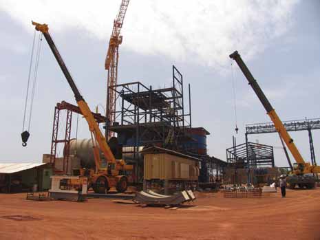
However, nothing in this sector is
more noticeable than the flood of
recent contract awards for gearless
motor drives for grinding mills. These
drives, which eliminate gearboxes or air
clutches by transmitting torque
between a “wraparound” motor and the
mill by means of a magnetic field in an
air gap between the motor stator and
rotor (the mill body itself), have evolved
into sophisticated control systems that
include not just the motor and drive
hardware but also power filtering,
over/under current protection, control
and supervision of hydraulic and lubrication
systems for the mill bearings,
braking and operator interface systems
and more. In spite of their growing
complexity, during the past several
months two of the major suppliers in
this sector have reported a steady
stream of orders for units rated up to
28 megawatts (MW) to drive large SAG
and ball mills. Siemens, for example,
announced:
• A €16-million order to supply two
18.3-MW gearless drives for 36-ftdiameter
SAG mills at Minera Penasquito
in Mexico.
• An order in November 2007 from CITIC
Heavy Machinery Group, Luoyang,
China, for gearless drive systems to
power five 40-ft-diameter autogenous
grinding (AG) mills that will be installed
at the Sino Iron project in
Western Australia. Siemens said the
28-MW output of these mill drives
makes them the most powerful available
in the market.
• An order announced on December 4,
2007, for gearless drive systems to be
used on a 40-ft-diameter SAG mill and
two 26-ft-diameter ball mills at Anglo
American Chile’s Los Bronces Development
project. The SAG mill is the third
40-ft unit to be driven by a Siemens
system, the other two being the Sino
Iron unit and another at Newcrest
Mining’s Cadia Valley mine in Australia. The Los Bronces SAG mill drive is rated
at 22 MW and the ball mill drives at
16.4 MW.
• A €20-million order on December 10,
2008 from Compania Aurifera Brisas
del Cuyuni C.A., a subsidiary of Gold
Reserve Inc., for gearless mill drives
for two 36-ft-diameter SAG mills at
the Brisas gold-copper project in
Venezuela.
• A €30-million contract from Xstrata
Copper in April 2008 for motors and
drive system to be used on a SAG mill
and two ball mills at one of its South
American copper mines. The SAG mill
drive package is rated at 21 MW; the
ball mill drives at 16.4 MW.
• An order in May 2008 valued at more
than €20 million from Aurox Resources
Ltd. to supply gearless drives for a
34-ft-diameter, 14-MW SAG mill and a
26-ft-diameter, 17-MW ball mill for an
iron ore project in Western Australia.
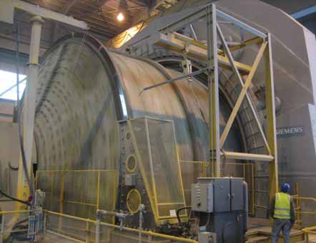 A Siemens GMD powers this 40-ft-diameter SAG mill.
• That it had, in early 2007, completed a
$41-million order for installation and
commissioning of four gearless ball mill
drive systems at the Cerro Verde mine
expansion project in Peru. ABB also
supplied four high pressure grinding roll
drive systems, each driven by two of its
water-cooled ACS 1000 drives, including
transformers and motors.
• An order worth about $27 million in May
2007 from Boliden to supply 22.5-MW
gearless drive systems for the Aitik mine
in northern Sweden, where they will
power two 38-ft AG mills. The scope of
the ABB contract included spare parts,
network studies, installation supervision
and commissioning. The new concentrator
is scheduled to start operation in
2010, and will completely replace the
current grinding plant.
• A contract in November 2007 totaling
more than €17 million from Potgietersrust
Platinum (PPRust), Anglo Platinum,
for gearless mill drives for the PPRust
North expansion project. The contract
called for two GMD systems with preengineering,
ring motors with VPI insulation
(vacuum pressure impregnation),
transformers, E-houses, cycloconverters,
spare parts, shipping coordination,
cabling and power factor correction and
as well as material delivery, supervision
of installation, and commissioning.
• A $25-million order from Anglo Platinum
in December 2007 to deliver two
gearless mill drive systems for the
Mokopane mill, 280 km northeast of
Johannesburg, South Africa.
• A contract valued at more than $13
million from General Moly Inc. for a
13-MW gearless mill drive system for a
36-ft SAG mill. The order is for General
Moly Inc.’s Mount Hope molybdenum
development project in Nevada, USA.
• A letter of award In April 2008 from
Rosemont Copper Co., a subsidiary of
Augusta Resource Corp., for a $42-million
contract to supply three gearless
mill drive systems—one rated at 16 MW
for a 36-ft-diameter SAG mill and two
16-MW systems for 26-ft-diameter ball
mills—at the Rosemont copper mine
near Tucson, Arizona, USA. With this
announcement, ABB noted that it had
won contracts for a total of 11 installed
or ordered GMD units in the U.S.
There are a number of factors driving
this trend toward GMDs, particularly
in applications involving large AG,
SAG or ball mills. Near the top of the
list is a GMD’s capability to easily tailor
SAG mill speed to changing feed characteristics;
or in the case of a ball mill,
to control downstream circuit feed
rates. The advantages of lower maintenance
requirements, user-friendly
man/machine interfaces, precise positioning
capabilities and the prospect of
longer service lives due to fewer
mechanical components are also powerful
incentives.
From a maintenance point of view,
the low-speed positioning, anti-rocking
and frozen charge protection capabilities
of gearless drives are important
features. Apart from the elimination of
a separate inching drive to position the
mill for liner replacement or other service,
the inch/creep functionality of
gearless systems reduces the problem
of precise positioning to a few button
pushes. For example, as explained by
authors Norbert Becker and Kurt
Tischler in Siemens’ Metals & Mining
newsletter, with Siemens’ gearless mill
drive “…inching for positioning of the
mill to gain access to liners for replacement
takes place at 1.2 rpm. Since it is
a maintenance mode of the mill, inching
is operated from the local control
panel or MLCP. The operator indicates
the angle to be turned on the MLCP
(inching angle). To simplify selection of
the correct angle, the selection is based
on the number of bolts around the circumference
that the mill is to be
turned. Inching starts and stops with a
balanced mill charge.”
The gearless drive turns the mill and
lifts the material. The angle at which
the material cascades the first time is
measured and stored. The drive turns
the mill by the requested angle, and
then overturns the mill by the cascading angle. Upon reaching the sum of
requested and cascading angle, the
drive stops the mill and changes the
direction of rotation. The gearless drive
turns the mill back by the cascading
angle, switching over to torque control.
It turns the torque-controlled mill back
until the torque is zero. With the torque
at zero, the charge is balanced and
there are no oscillations.
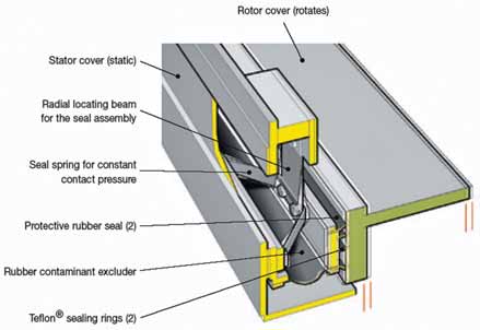 ABB’s greaseless seal system for its GMDs provides an early-warning notification of the end of service life
on its
Teflon-to-metal sealing tracks.
The authors also explain the system’s
“frozen charge shaker” feature.
Under certain conditions, a mill’s
charge can solidify during a standstill
and the “frozen” charge can stick to the
mill body. This condition can damage
the mill if the solidified charge is lifted
during start and falls from the upper
part of the mill.
The frozen charge shaker function
can be initiated at the local control
panel, where a key-operated switch
must be activated to allow this mode of
operation. When the start button is
pressed, the drive turns the mill, lifts
the charge up to the maximum safe
angle for the mill, and moves the mill
up and down. It then returns the mill to
a balanced position, lifts the charge on
the other side up to the maximum safe
angle, and again moves the mill up and
down. When this sequence is completed,
the operator can verify whether
there is still a frozen charge by starting
the mill in any of the operation modes.
According to the company, the total
time for breaking a solidified charge
with the shaker feature, including
preparation and a test run afterwards,
is about 30 minutes.
Not surprisingly, ABB’s gearless
drive systems also have built-in lowspeed
controls for inching, an antirocking
software package, and a torque
monitoring system to prevent damage
from frozen mill charges. ABB also
touts the robustness of its gearless
drive design, emphasizing that “robustness
means concentric” when referring
to the air gap between the drive system’s
rotor and stator. Maintaining the
proper air gap—considered the most
critical dimension for this type of
drive—is dependent on rotor/stator
roundness and concentricity. Deviation
in concentricity is the source of magnetic
pull imbalance around the air
gap, and is consequently critical to
force distribution throughout the integrated
mill/GMD/foundation system.
The air gap helps overcome roundness
and concentricity variations that arise
from heat, load and process conditions.
For instance, with a nominal air gap of
16-17 mm for large SAG mills, the ABB
design allows for considerable eccentricity.
The gap is monitored by nine
noncontact, capacitive sensors located
inside the stator, which also inform the
operator of air-gap status at standstill.
Sealing the air gap and rotor/stator
surfaces against outside contaminants
has always been a concern with gearless
drive suppliers, and each GMD supplier
has their own approach. ABB has developed
an axial greaseless sealing system
that employs Teflon to minimize friction.
The spring-loaded design, according to
the company, seals out particle and fluid
contamination, and the Teflon-to-metal
seal has a 16,000-20,000 hour service
life. The sealing tracks can be inspected
through access ports. Sensors monitor
seal height and indicate end of seal life
1,500 hours in advance.
Comparing Drive System
Characteristics
Although GMD capabilities seem to
present an unbeatable feature lineup,
particularly for large AG/SAG or ball
mills or plants that need process optimization
or expect future throughput
increases, there are a number of factors
that come into play when deciding what
type of drive system should be selected
for a specific application. Not every
operation will require the high power
ratings and extended functionality
offered by GMDs, and not every project
owner can afford the cost or cope with
the complexity of these systems.
A presentation at the 2007 Annual
Meeting of the Society for Mining, Metallurgy and Exploration (SME)
offered an excellent rundown of comparative
issues when selecting a grinding
mill drive system. The authors,
Markus Ahrens and Johannes Gonser of
ABB, explained that “The question of
what drive system is optimal for SAG
and ball mills is project specific and
depends on the plant layout and the
design of the grinding circuit. When
drive systems are compared the main
criteria are operating characteristics
(fixed speed or variable speed, starting
behavior, interaction with the network,
harmonic distortion), maintenance
aspects (reliability, wearing parts,
downtime) and cost issues (capital
expenditure, power factor and drive
efficiency impacting energy cost, maintenance).
In addition, drive systems
show differences in other design and
operational issues such as inching and
creeping, load sharing (if dual pinion
drives are used), frozen charge protection
and space requirement.
“When determining the mill size and
the drive type the required process
power needs to be calculated based on
design process specific energy (kWh/t),
plant size (t/d) and total milling process
power,” said the authors. “The required
process power is divided into circuits
and numbers of mills within a circuit,
followed by the selection of the mill
sizes to fulfill the requirements. The
optimal drive type can only be selected
after determining the mill size, the need
for variable speed and the characteristics
of the electrical system of the plant.
There are a number of mill drive options
that should be measured against the
range of functions and capabilities
required by a specific project.”
The universe of drive systems for
grinding applications includes a halfdozen
or so different technologies ranging
from fixed-speed systems (slip-ring
and synchronous motors) to variablespeed
(slip energy recovery drives, load
commutated inverter or LCI drives,
cycloconverter drives and gearless mill
drives). Briefly summarized by the
authors, the characteristics of each
type follow:
Slip-Ring Motors—High-speed drives
generally used for smaller mills, but can
be used on larger units as well. They
offer low capital costs compared with
other systems and are robust against
voltage dips, but power factor is generally
low and drops further in partial load
conditions. A separate device is required
for inching and creeping with
these systems. Theoretically, speed regulation
can be achieved with the starting
resistor but this is an inefficient
solution.
Synchronous Motors—Includes highspeed
motors that drive the pinion
through a main gearbox, or low-speed
motors driving through an air-clutch
coupling. A clutch allows the motor to
be started uncoupled, but it can be a
high-maintenance item. With weak
power systems, reduced-voltage motor
starting is possible, and on dual pinion
drives each motor can be started separately,
reducing the impact on the power
system. Synchronous motors have a
high inrush starting current—400% to
600% of nominal current. The starting
torque depends on the motor design and
can’t be adjusted later on.
Slip Energy Recovery Drives—These
systems use slip ring motors and starting
resistors, thus limiting inrush current.
Speed is controlled by adjusting
slip resistance, generally achieved by
inserting resistance into the rotor circuit
and dissipating this energy into the
starting resistors—an inefficient
approach. So, rather than using the
starting resistor, the slip energy is converted
to direct current, inverted to the
frequency of the power system feeding
the motor, and then fed back into the
power system through a step-up transformer.
The use of these systems has
fallen sharply over the past decade, as
better solutions are now available at
comparable cost.
LCI Drives—Although these drives
can be used with both low-speed and
high-speed motors, the drives are highspeed
in nature and thus their use for
low-speed applications is limited.
Continuous operation at low speeds
(below 10% of normal speed) is not
advisable due to high torque pulsations.
Voltage Source Inverter Drives—
These drives can be used with both
induction and synchronous motors, do
not generate significant torque pulsations,
have a very smooth starting behavior
and are well-suited for weak
power networks. The power factor to the
network is high. They do not require
inching or creeping auxiliary equipment.
Cycloconverter Drives—Can be used
with both gearless drives and single- or
dual-pinion geared drives, using lowspeed
synchronous motors. Although
the technical features of the cycloconverter
remain the same when used with
both types of drives, system efficiency
is less with geared drives while maintenance
costs are higher due to the ring
gear.
As featured in Womp 08 Vol 5 - www.womp-int.com