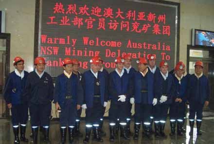
A crew from Yancoal Australia’s Austar mine visited a Chinese mine owned by Yancoal’s
parent company to learn about Longwall Top Coal Caving (LTCC) techniques.
Top Coal Caving Longwall Maximizes Thick Seam Recovery
Austar’s longwall system offers opportunities in seams thicker than
4.5 meters
By Greg Duncan, Glenn Sobey and Tim Clarke
Despite the technical and regulatory challenges associated with the introduction of brand new technology into the Australian industry, the first LTCC longwall successfully commenced production in September 2006. The longwall is operating at the Austar mine, which is owned and operated by Yancoal Australia, a wholly-owned subsidiary of the Yanzhou Coal Mining Co. of China. Yanzhou is part of the Yankuang Group.
Yanzhou Coal Mining operates six underground coal mines in the Shandong Province of China and each of these underground mines is operating LTCC longwalls. Combined, they produce approximately 40 million metric tons per year (mt/y). Yanzhou’s Jining No. 3 mine, at an operating depth of more than 600 m, produced more than 10 million mt in 2005, using solely LTCC production techniques.
The Austar longwall is extracting a seam thickness of up to 6.5 m with a working face height of 2.9 m. To date the operation is achieving 88% seam extraction with a recovery of 89% through the prep plant. There are tremendous opportunities both in Australia and worldwide to mine seams greater than 4.5 m thickness using this innovative longwall mining technique.
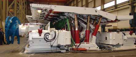
The LTCC Longwall face equipment was designed by a joint Chinese (Yankuang), Australian (Austar Management) and German (DBT) engineering team. The equipment was manufactured in Germany and supplied by DBT. Technical and Engineering support for the equipment was supplied by DBT Australia.
LTCC Introduction to
Australia
Located approximately 8 km from Cessnock
in New South Wales’ (NSW)
Hunter Valley, Austar extracts coal from
the Greta seam, which is a high-fluidity,
low-ash and low-phosphorous coal. Coal
mining in the region dates back to the
1880s with the commencement of mining
on what is now the Austar Lease’s
beginning in 1916 as the Pelton
Colliery. As the Pelton workings progressed
deeper it was recognized that in
order to continue mining in the increasingly
difficult conditions, the introduction
of longwall mining and increased
mechanization was needed.
In early 1979, a new shaft and drift was developed into three main heading roadways driven from the Pelton workings. The shaft and drift formed the access to the new Ellalong colliery which introduced the first longwall into the Greta seam in 1983, with production commencing in July of that year. A total of 17 longwalls were extracted from the Greta seam.
During the extraction of the 18th longwall block there was a fire which resulted in the mine being sealed in December 2003. In February 2004, the mine was excavated and recovered. The longwall equipment was destroyed and sealed as part of the recovery.
Yanzhou Coal purchased the lease and assets and renamed the mine the Austar Coal mine in December 2004. Development roadway driveage at Austar recommenced in June 2005.
In 2001, Yankuang Group commissioned
the Commonwealth Scientific and
Industrial Research Organization (CSIRO),
Australia’s national science agency, and
the University of New South Wales (UNSW)
to carry out a pre-feasibility study into Top
Coal Caving in Australian conditions. The
study investigated areas such as:
• Seam characteristics–thickness, dip
and depth;
• Stress conditions;
• Economic implications of the new system;
• Expected operational issues; and
• The overall suitability of Australian coal
seams for LTCC extraction.
The study identified an estimated resource of 8 billion mt of coal suitable for LTCC extraction, predominantly in the states of NSW and Queensland. In the pre-feasibility the Austar lease was identified as having a high to medium potential for a LTCC operation.
As part of the study a risk assessment
was carried out on the Application
of LTCC in Australian Conditions. The
general view of this risk assessment was
that there was no significant issue stopping
the implementation of the LTCC
method in Australia. In fact, LTCC was
viewed to have many advantages compared
to high reach single pass longwalls.
The main points to come out of
the risk assessment were:
• The need for a powered roof support for
the main gate roadway;
• Specifically designed shields to control
the caving of the top coal;
• The need for the site selection process
to include geotechnical suitability;
• Poor ventilation for rear AFC resulting
in an accumulation of dust and gases;
• The rear AFC drives exposed to gas
made from the caving coal with limited
ventilation;
• Dust made on the face and the exposure
of the workforce; and
• Heat due to additional AFC drives on
the face.
From this risk assessment the two main developments were the design and construction of the main gate roadway support and the move to two legged supports for better face and caving control.
As well as CSIRO and UNSW, DBT Australia was also involved in the prefeasibility study after they too recognized the potential for a LTCC longwall in Australia. DBT personnel participated in the risk assessment process such that practical solutions to identify risks could be adequately assessed. DBT ultimately developed the new shield and support designs.
The Austar mine is acknowledged in Australia as geotechnically one of the more challenging mining areas. The highly structured and stressed ground and 900-mt/h constrained coal clearance system was considered by many to be the ideal site for the introduction of the LTCC to the Western World.
The senior management of Yanzhou Coal had unquestioned belief in the LTCC system and proceeded with the project with the mind set that, “once we demonstrated that it can work at Austar the industry will realize that it will work anywhere.”
Regulatory Approval
The introduction of LTCC into the
Australian coal mining industry was a
collaborative achievement between
Australian, Chinese and German engineers.
The equipment was customized
to meet the design requirements for
operating within the NSW regulatory
framework. Both the mining unions and
the Department of Primary Industries
safety divisions were integral in the
process and were involved from the early
stages of the project’s inception. Risk
management included representation
from DBT, Austar, Yancoal, the local
union, and government mines inspectors
(for scoping sessions).
Due to LTCC being completely new to the Australian coal industry, key personnel visited the Yanzhou Coal’s Chinese operations to gain first hand familiarity with the LTCC system. The key Austar personnel were senior management, statutory engineers, longwall coordinator, longwall team, operators, mechanical tradesmen, electrical tradesmen, and crew leaders. In addition to the Austar personnel, Yancoal took the proactive step of inviting government mines inspector-mining, government mines inspector-mechanical, a union official and the local and district safety inspectors.
These visits allowed participants of the risk assessments to understand the practicalities of the operating LTCC system and what the potential risks were with the rear AFC system. Separate to these visits, there were also visits to China by representatives of DBT.
There was an additional visit by Austar personnel to DBT’s facility in Germany where the Austar longwall equipment was fabricated. These compatibility, hosing and piping trips allowed the equipment to be modified to fit the site specific issues at Austar. This included a complete redesign of the valving and fit out of the complex hydraulics on the shields and inclusion of a 420-bar high pressure set system to better control the expected face conditions.
The risk management process continued with the delivery of the LTCC equipment to DBT in Australia. A 50 m mini-build was assembled at the DBT workshop at Hexham near Newcastle, including the shearer, BSL, and monorail. This mini-build allowed for further familiarization and operational risk assessments to be completed.
From the risk management process Austar was able to develop a complete set of operating and maintenance procedures suitable for the operation of the LTCC longwall. Using these procedures and the mini-build, Austar was able to train its operating and maintenance crews prior to the equipment coming on site. DBT Australia was also involved in the training supplying facilities and technical staff.
From the purchase of a distressed site with limited equipment, staff and roadway development, the mine recommenced operations in June 2005 and LTCC extraction in September 2006.
What is Longwall Top Coal
Caving?
Due to the inherent operational problems
and high costs associated with the
multi-slicing longwall method, and the
legislative requirement from the central
government of a 93% (minimum) recovery
rate, LTCC was introduced to the
Chinese coal industry in 1982 (based
on the European soutirage methods).
The European soutirage methods
allowed for extraction of up to approximately
9-m thickness with only one set
of panel development roadways and
infrastructure. From these initial methods
the Chinese industry has gone on to
develop the LTCC into a distinctly different
method with improved efficiency,
safety and production rates.
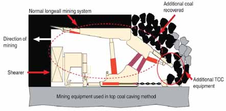
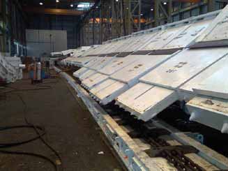
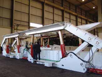
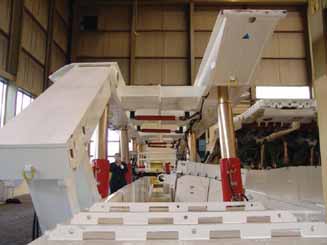
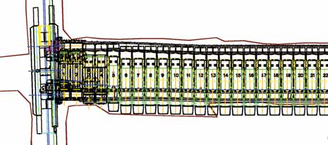
In the simplest description, LTCC is a conventional retreat longwall face with a second armored face conveyor (AFC) towed behind the shields to recover coal that would otherwise fall into the goaf [gob] and be lost (See simplified LTCC Longwall schematic on previous page). The roof supports are of a modified design incorporating a system of hydraulically operated tail-canopies at the rear of the support which can be moved up and down to allow the broken coal in the goaf area to spill onto a second AFC. This process is allowed to continue until all of the coal is recovered and waste rock appears. At this time, the tail canopies can be lowered and “gates” shut, pulling the AFC forward to stop recovery of product from the goaf. The rear AFC pan line is connected to the shields via a chain and hydraulic ram. The chain gives flexibility while the ram drags the pans in behind the shields.
To allow the rear AFC to load onto the BSL, the BSL is extended back into the goaf area. To facilitate this, the LTCC system uses a purpose designed main gate roadway support. This support, consisting of five linked shields, extends to the rear of the face and allows for the BSL to be extended for the rear AFC. Although this shield sits in the main gate roadway it is heavily reinforced to protect the BSL and rear of the face from the goaf.
Greta Coal Measures
The geology at Austar can be summarized
as the Greta coal measures overlaid
by massive sandstones. The immediate
15 m to 20 m of Greta seam roof
comprises the thin Pelton coal seam
(less than 300 mm) and highly variable
interbedded siltstones, sandstones,
grits and conglomerates. This variation
can lead to variable roof strengths. The
average UCS of the immediate roof strata
varies between 20 and 60 MPa but
this increases to 80 to 100 MPa within
the overlying sandstones. The immediate
floor (1 m or less) of the Greta seam
is a soft mudstone (UCS of 20 MPa)
underlain by medium grained sandstones
with UCS values of 70 to 80
MPa.
The Greta seam is characterized by:
• Low strength (5 to 8.5 MPa);
• Irregular and persistent inseam shear
zones;
• Zones of highly cleated and jointed
coal;
• Horizontal stresses averaging 2.5 times
the vertical stress at depths of 400 m
to 650 m;
• High permeability; and
• A number of thin marker bands in the
upper part of the seam.
The roof and rib conditions are extremely variable with development targeting the lower marker band as a stable roof horizon. This horizon leaves approximately 1 m of coal on the mudstone floor. The high permeability has resulted in high rates of seepage, from the flooded old abandoned workings that are immediately up dip of Austar.
LTCC Installation
The rear tail canopies and rear AFC of
the LTCC longwall require an installation
face 8.5 m wide widening out to 9.5 m
at the gate ends. This is 1-m wider than
the installation faces used at Austar
prior to the introduction of LTCC. The
installation face was considered a high
business risk due to the weak and highly
structured nature of the coal seam
and the high stress environment. Under
a previous operator, 7.5-m wide longwall
installation faces had to be abandoned
or driven using a strip and install
method. Both events resulted in major
delays to the operation. To create a serviceable
9.5-m-wide excavation was a
major challenge.
After considering the minimum requirements necessary for successfully installing the longwall, the decision was made to drive the installation face to a final width of 8.5 m, increased to 9.5 m at the gate ends. To safely maintain the roadway for the duration of the installation the initial pass of the face was driven with heavy secondary support including more than 450 10-m, 80-mt grouted cable bolts. Despite this heavy support there was guttering at the face. In addition, 17 extensometers were installed on the first pass. It was the analysis of this monitoring that allowed the face to be mined to its final width. An additional 450 grouted cable bolts were installed in the widened area.
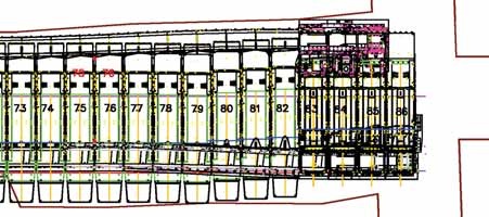
With the completion of the installation face to the required width, the LTCC equipment could be installed onto the face. Due to the need to maintain a solid coal barrier between the new longwall block and the site of the 2003 fire the first block is only 150 m wide. Future blocks are designed at 220 m. Due to this reduced width only 79 of the 118 run of face shields supplied by DBT were installed on the face. When the longwall is relocated to the A2 block the remaining equipment will be incorporated into the face.
Initially the longwall shields were to be transported into the face using LHD’s and chariots. Due to width and height restrictions through the old Ellalong workings, however, an alternative method of transport had to be found. Boart Longyear’s LWC50 shield carriers were hired and work began on transporting the shields the approximately 6.5 km from the bottom of the Ellalong drift to the A1 install face. These carriers proved so successful and popular with the operators that they will be the carrier of choice in the future. Once on the face, the shields were positioned using a Petito Mule.
The shields were positioned between the already installed front and rear pan lines. The pans were transported and positioned using an ED10 LHD and a pan picker. Once the shield was in position the two pan lines were connected. The AFC chains were both installed using a winch and rope.
The installation of the face equipment continued with the installation of the six-legged gate end supports, the main gate roadway support, BSL and the shearer. Each of these areas required detailed planning from transport down the restricted Ellalong drift to final commissioning.
The installation of the equipment was very complex at the main gate end. To ensure an optimized timeline, it was deemed necessary to install face pans and shields from the tailgate end while simultaneously building the main gate arrangements and roadway shield. Despite the complexity and original designs, the first ever LTCC face was installed and commissioned without a major incident or delay.
Equipment Innovations
The LTCC for Austar not only was the
first new generation top coal caving face
but also had a number of Australian first
and world first innovations. DBT was
assigned a single contract in which it
coordinated all sub-contractors which
included the pump station and electrical
system. The longwall face shields
had 20 valve functions and required
DBT’s new generation of shield control
unit, the PMC-R. This was the first
installation in Australia and third in the
world. The PMC-R due to its increased
processor speed functionality and high
speed bus is the only control system
available to undertake the complex task
of a fully automated LTCC face.
Austar was also the site of the first new generation DBT mid- to low-seam shearer, the EL2000. The building blocks for this shearer of automation control AC drives and haulage are well proven. Added to this was DBT’s new generation ranging arm. The horizon control of the face at Austar is among the most complex operating requirement worldwide as both the main gate and tail gate areas are needed to be ramped up and, to maintain a very stable face, the shields were moved across in very close proximity to the cutting drum and flippers extended. Over the last three months of operation automated horizon control has been successfully implemented on the basis of “repeated roof” which allows the shearer operators to remain on the clean air side of the ranging arm. AFC control for LTCC is also paramount. Fast response and feedback on potential overloads is required and Austar was one of the first mines in Australia to use DBT’s next generation of CST drive control for PMC-D. With the need for restricting coal flow onto the belt conveyor to around 1,000 mt/h it is also important to have feedback from the stageloaders to ensure coal production overload does not occur. Again, this has been successfully implemented.
The LTCC face at Austar has had the combined innovations of a totally new longwall mining system which required the design of three totally different longwall shields, substantial innovation around the gate end discharge, and probably the world’s most advanced level of automation where each of the major equipment segments is effectively interacting with each other to enable effective automation and protection.
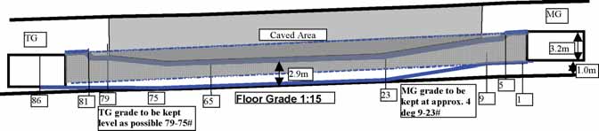
Commissioning and
Production
In September 2006, the Australia LTCC
face commenced production. The face
conditions at Austar are not easy to
work, with soft coal and weak floor as
mentioned previously. These conditions
had to be carefully managed at the commencement
of production. Particularly
as the supports had to be brought under
a lip at the start to achieve the cutting
height of 2.9 m, from an installation
road at 3.2-m height in addition to profiling
down to the seam floor. This was a
difficult 3-D profile which was cut with
the shearer manually as it was beyond
the scope of the automation.
The equipment as specified and delivered is capable of outputs in excess of 10 million mt/y. Coal clearance constraints of the mine will limit this to 3 million mt/y. It is fair to say that if the equipment was purpose specified for the Austar mine, certain components and capacities would be much smaller. As a result the equipment is tighter than it could otherwise be.
Several operational issues with the
main gate end included:
• Gate-end roadway support;
• Restricted access to face due to the
width of gate road support;
• Roadway alignment is critical despite
limited ability to steer the support;
• Complex nature of the support requires
manual control to advance;
• The management of creep is critical
due to the minimal clearances; and
• Access to the face via a bridge over the
exposed BSL.
Some important operational requirements
at the main gate end shields
included:
• The need to cover the AFC drives
extends the shields into the roadway;
• Horizon control for the connection
between the gate end shields and the
roadway support;
• Restricted access at the main gate end
due to the size of the drives;
• Roadway horizon and cleanliness for
advancing the front AFC; and
• Potential clash point between the shields
and top of the AFC drives due to the
build up of fines under the drives.
There were also issues with the tailgate
end, which included:
• The need to cover the AFC drives
extends the shields into the roadway;
• Restricted access at the tail gate end
due to the size of the drives;
• Horizon control for the advancing of the
front AFC drive; and
• Potential clash point between the shields
and top of the AFC drives due to the
build up of fines under the drives.
The caving characteristics have proven favorable to LTCC. The goaf is forming tight to the rear of the shields and 88% of the seam is being recovered. Dilution is readily achieved if not carefully managed and optimizing the caving cycle is continuing as a priority. Currently a mix of manual and automated caving is used. Despite the learning curve, Austar is still achieving 89% recovery at the wash plant. The end goal is to fully automate the caving cycle. Currently caving is controlled manually in China.
The high pressure set (420 bar) system has allowed Austar to better manage the face conditions without compromising the break-off line of the top coal. This has been a very successful part of the system which can be supported by the fact that over the 2006 Christmas holiday, the face stood for 10 days with no deterioration of the top coal or face. Certainly the 1,100-mt capacity two-leg shields have proven that they can control a soft coal environment extremely well. Whereas in the past, the 650-mt supports were definitely inadequate and face slumping and guttering was regularly experienced.
To maximize the caving tons, the cutting horizon selected was the floor of the seam to 2.8 m. While maximizing the tons, this horizon has meant that the main and tailgates have to be graded to fit the gate-road horizon which was developed with 1 m of coal on the floor. This coal was left as it was nearly impossible to develop on the stone floor due to water and the soft mudstone in the floor bogging the equipment. Maintaining the correct horizon has been an important part of the commissioning process and to date has been managed with some degree of success despite the relatively inexperienced workforce.
The management of spillage and goaf flushing around the rear AFC drives and the rear of the gate end shields requires careful management. The current arrangement provides poor flushing protection between the six-legged gate shields. In China, the area is controlled using mesh installed over the shields. The same technique is used at Austar utilizing pre-cut lengths of steel chain mail mesh. With care the technique is effective at preventing most of the spillage. The drive areas still require regular inspection and cleaning.
Face automation with the LTCC system has been successful up to a point. The caving process has been automated and the shearer is handling the complex profile despite availability issues with the horizon control systems.
The automation of the main and tail gate ends is too complex and beyond the capability of current control systems. The length and complexity of advancing the gate end shields require that this is done manually with spotters to ensure the canopies don’t become interlocked. A limit of 50% advance had to be placed on the gate support advance to prevent damage and downtime with crossed rear caving shields and side shields. The operating crews received rigorous training in these sequences and they are closely followed and enforced to prevent delay and damage. Advancing the eight-legged main gate roadway shield has similarly proved a complex and ever changing task that is currently considered impossible to automate. The shield is advanced manually to control the alignment and potential clash points.
The services transition from monorail via the BSL onto the face proved to be an issue that couldn’t be properly identified in the workshop during the compatibility testing and mini-build. Extensive modifications were made to the hose and cable handling system to give better access to the face for the crews and to protect the services from damage. The majority of the work was carried out during the Christmas holiday maintenance shutdown period and proved successful.
To ensure a smooth commissioning and ramp up into production the main gate and tail gate roadways have been heavily supported with additional grouted cable bolts. According to those who were at the mine under previous operators, this additional support in the roadways has had a big impact in maintaining roadway integrity.
The tail-gate end shields sit in the center of the roadway making the installation of standing support in the tail gate roadway impractical. This potentially leads to the requirement of a tail gate roadway free of standing support. This was thought impossible at Austar under previous operators but to date is being successfully achieved.
Face conditions experienced during the mining of the A1 block have been generally good. There have been minor delays due to stress on the face as well as delays due to loss of clearance due to floor heave ahead of the longwall. Compared to the delays suffered during the Southland days these delays have only had a minor impact on the operation. The use of modern two-legged supports fitted with flippers has been a big improvement from the Southland longwall which combined a number of different shield designs on the one run of face.
With exception for around the drives, rear AFC access has not proven to be an issue to date. Access to the drives in maintained by close supervision and enforced high face standards of cleanliness around the drives. By January, the Austar LTCC longwall was achieving 99% of budgeted production, with 102% achieved in February. The crews are gaining experience and minor modifications were made to equipment as needed.
Spontaneous Combustion
Due to the history of the site and the
propensity of the Greta seam to spontaneous
combustion there has been a
strong focus on monitoring and preemptive
control at Austar. Some of the
controls that have been put in place at
the Austar operation include:
• The pro-active inertization of the goaf
and pressure balancing of seals using
an on-site 1,800 m3/h nitrogen plant;
• The workforce has been retrained in the
detection of signs of spontaneous combustion
targeting the early stages of the
oxidation process;
• The environmental monitoring system
of the mine has been upgraded, inclusive
of an on-site gas chromatograph
and real time monitoring; and
• An external consultant experienced,
dedicated and focused to monitoring
gas trends has been contracted to
review and monitor results.
The mine has introduced some innovations to spontaneous combustion management which are receiving some real focus from operators from other high prone seams in Australia. In addition to these controls the LTCC has the advantage of recovering the majority of the coal seam leaving a minimum of remnant coal in the goaf to oxidize. To date the results of the monitoring and inertization have been promising with gas levels trending well below the management plan trigger points in the newly formed goaf behind the LTCC face and the sealed goaf area.
The Next 12 Months
The first longwall relocation from the A1
to A2 blocks will occur in the third quarter
of 2007 and is shaping up to be as
big a project as installing the LTCC
equipment for the first time. Some of
the issues identified with this Australian
first are:
• The roadway width necessary to safely
and efficiently recover the equipment
from the face;
• The level of support necessary to maintain
this roadway during the relocation;
• The sequence for recovering the main
gate roadway shield; and
• The sequence for recovering the sixlegged
gate end shields and the rear
drives and the standing roof span required
to be held open during recovery.
Austar is taking a very conservative approach to the ground support for the take off roadway with a heavy support pattern planned. In particular the gate end areas will be heavily supported with post grouted cable bolts. To give access to recover the rear AFC drives, chain and pans the gate end shields will need to be recovered. This will open up a roof span of approximately 14 m to 15 m adjacent to the goaf edge.
Prior to and after the relocation there will be fine tuning of the automation and cutting cycle to maximize the efficiency of the LTCC system. In both cases it will be the advancing of the gate end areas that will be the area of primary focus.
The conditions in the tailgate will be a key factor for the success of the next block. With the increased stresses of an adjacent goaf there is expected to be floor heave in the tailgate roadway. This will need to be managed to ensure that the clearance and horizon is to be maintained for the tail gate end shields and AFC drives. To date the most effective control of the horizon has been a paint mark that is maintained on the rib at top of drum height. Additional controls such as trenching and cabling the floor are being investigated.
The longwall will require re-handing due to the layout of the blocks in the future mining areas. While the next two blocks do not require the wall to be rehanded, this will be a major undertaking and planning is already underway. Away from the longwall, Austar is committed to a program of improvements to the existing coal clearance system, which in some areas dates back to the original Ellalong installations. These upgrades will allow the LTCC system to achieve even higher productivity.
Looking Toward the Future
The increase to the ratio of longwall
extraction to roadway development guarantees
the long term future of the LTCC
at the Austar mine. This being said there
is always room for improvement. A number
of the long term projects that are currently
being investigated include:
• The redesign of the six-legged gate end
special to a four legged shield to improve
operational efficiency, allow for
automation and better control flushing.
• The redesign of the Rear AFC drives to
reduce their overall size. This will reduce
the overall length of the gate end
shield canopies.
• The redesign of the Rear AFC to BSL
transfer, once again to minimize the
overall length of the canopies required.
• Investigate changing the development
horizon to the base of the seam to
remove the gate end ramps and associated
horizon control issues.
• The widening of the main gate roadway
to 5.2 m from the current width of 5 m
to improve the clearances for the gate
end and roadway shield. This is planned
for Austar block A3 with the mobilization
of a Joy wide head continuous
miner which will cut a 5.2 m roadway.
The modifications and improvements on the LTCC equipment are being carried out in close partnership between DBT, Austar and Yancoal and will no doubt result in an industry-leading extraction system capable of maximizing the value of the operation.
With a proof of concept and the capacity for improved efficiency the LTCC system at Austar is set to take the mine into its centenary with industry leading innovation and technology. With Yankuang Group of China and DBT Engineering working together there is little doubt that the LTCC system will become as important to the Australian and world coal industry as it is in China.
Author Information
Duncan is Austar Coal’s general manager. Sobey is an Austar Coal mining
engineer. Clarke is systems project manager for longwall capital equipment,
DBT Australia. This article was adapted from a paper Duncan and Clarke presented
at Mining Media’s Longwall USA 2007 Conference & Exhibition, which
was held during June in Pittsburgh, Pa., and cosponsored by E&MJ
and Coal Age. The complete paper along with photography is available
at www.mining-media.com