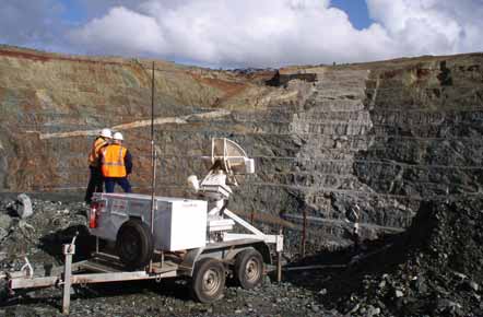
GroundProbe's Slope Stability Radar system, shown here, has a range of up to 450 m from the target slope.
Stabilizing Influence
With worker safety and overall productivity at stake, mines are paying more attention
than ever to slope stability concerns. New technology can provide most of the answers.
Few companies engaged in surface mining are immune from slope stability problems of varying severity, with major pit wall failure incidents over the past several years affecting leading producers that have included Barrick Gold, Freeport McMoRan and Rio Tinto, as well as nexttier operators such as Cameco and Newcrest, to name just a few. Large-scale wall failures can result in millions of dollars of expenses for additional excavation, haulage and revised mine planning; adversely affect annual production rates and corporate earnings; render existing ore reserves inaccessible; or may even spell the premature end of a mine’s life when they occur during periods of low metal prices. Not all slope stability problems, however, are large-scale events; failure or slippage of retaining walls, for example, can cause problems for crusher stations, roads and other mine infrastructure.
With so much at stake when it comes to maintaining stable pit walls and slopes, it’s not surprising that there are plenty of tools including both hardware and software products, as well as a large body of ongoing research into improved methods of monitoring, analyzing and applying ground-movement data, that can be used to prevent or minimize possible damage. It’s beyond the scope of this article to delve into every facet of slope stability technology, but it will touch upon some practical aspects as well as recent developments at the “high” end of the technology spectrum, where so-called observational systems that include radar, GPS and laser scanners are competing for industry acceptance and market share against more conventional instrumentation-based systems such as extensometers or crack meters.
Perhaps the most basic tool in slope stability analysis is simply knowing what to look for. In 2001, NIOSH Engineer Jami M. Girard published a paper1 that describes common geologic causes of pit wall failure and their visual clues. According to Girard, in order to determine which failure modes are possible at a particular operation the geologic parameters in various sectors of the mine must be quantified. Collecting information such as orientation, spacing, trace length and shear strength with respect to major structures, and other geologic features is an important key to determining failure potential. The basic failure modes that may occur include:
Plane Failure—Plane failures occur when a geologic
discontinuity, such as a bedding plane, strikes parallel to the slope face and
dips into the excavation at an angle steeper than the angle of friction.
Wedge Failure—Wedge failures occur when two discontinuities
intersect and their line of intersection daylights in the face.
Step Path Failure—Step path failure is similar to plane
shear failure, but the sliding is due to the combined mechanisms of multiple
discontinuities or the tensile failure of the intact rock connecting members
of the master joint set.
Raveling—Weathering of material and expansion and contraction
associated with freeze-thaw cycles are principle causes of raveling. This type
of failure generally produces small rockfalls, not massive failures.
Toppling Failure—Toppling can occur when vertical or
near-vertical structures dip toward the pit.
Girard cautioned that even the most carefully designed slopes may be subject
to instability. Acknowledging that slope failures may occur and knowing what
the warning signs are can contribute to the safety of the operation. Some of
the more common warning signs of slope instability are:
Tension Cracks: The formation of cracks at the top of a slope
is an obvious sign of instability. Cracks form when slope material has moved
toward the pit. Since this displacement cannot be detected from the pit floor,
it is important to frequently inspect the crests of highwalls above active work
sites.
Scarps: Scarps occur where material has moved down in a vertical
or nearly vertical fashion. Both the material that has moved vertically and
the face of the scarp may be unstable and should be monitored accordingly.
Abnormal Water Flows: Sudden changes in precipitation levels
or water flow may also precede slope failures. Spring run-off from snow melt
is one of the most obvious examples of increased water flow that may have adverse
affects on slopes. However, changes in steady flow from dewatering wells or
unexplained changes in piezometer readings may also indicate subsurface movement
that has cut through a perched water table or intersected a water bearing structure.
Changes in water pressure resulting from the blockage of drain channels can
also trigger slope failures. Water can also penetrate fractures and accelerate
weathering processes. Freezethaw cycles cause expansion of waterfilled joints
and loosen highwall material.
Bulges or Creep: Bulging material or “cattle tracks”
appearing on a slope indicate creep or slow subsurface movement of the slope.
Other indicators of creep can be determined by looking at vegetation in the
area. While most mines do not have vegetation on the slope faces, movement of
trees at the crest of a slope can be an indicator of instability.
Rubble at the Toe: Fresh rubble at the toe or on the pit floor
is a very obvious indicator that instability has occurred.
Radar, Lasers and More
A scanning radar system called Slope Stability Radar (SSR) has been used at
a number of mines for monitoring slopes using differential interferometry.2
SSR scans a slope both vertically and horizontally for deformations at a rate
of 10°/second over a range of ±60° vertically and 340° horizontally,
and can operate at up to 450 m from the target slope. Line of sight displacement
can be measured to ±0.2 mm without the use of reflectors. In operation,
the system produces an image showing spatial deformation relative to a reference
image for the entire slope scanned. The displacement history of each point in
the image can be plotted.

Neal Harries, GroundProbe's principal geotechnical engineer, has worked with most SSR installations over the last 18 months compiling data on experience that allows excellent benchmarking of SSR applications, and also has developed customer- training modules for slope instability risk management using the SSR, understanding and analyzing SSR data, and help in setting the alarms which can be critical for the success of the SSR application. Additional geotechnical support includes consultancy services in analyzing client data, back analysis of failures they have observed and SSR optimization.
“The radar gives users real time submillimeter measurements of rock wall movements over the entire face of a wall. This all weather system doesn’t require any contact with the wall, which is an unprecedented tool for the management of risks associated with slope stability,” said Harries.
Mining operations also can use SSR to optimize productivity as well as safety. For example:
• A Nevada gold mine was able to anticipate a 30,000-mt failure which
blocked a haul road leading into the main entrance of the mine’s underground
operation. The SSR provided more than five hours of warning, allowing for the
evacuation of all underground personnel and nearby equipment. Post failure,
the SSR was used to monitor the specific area, allowing the mine to confidently
allow underground personnel to return to work.
• A Western Australian metalliferous mine extended the operational life
of the pit by an additional six months using the SSR to critically monitor walls
as mining was extended beyond the initial mine design.
• An iron ore mine in South Africa used the SSR system to safely mine
on top of a large cave system and relied on the system’s data to minimize
delays in production.
Leica Geosystems recently introduced its new GMX901 GPS receiver, which it claims is well suited for precision monitoring of sensitive structures. The GMX901 is housed in a water, heat, cold and vibration resistant unit that can be mounted on a variety of structures at mines, slopes and dams. The system, according to the company, connects seamlessly to Leica’s Spider Network— advanced GPS processing software for coordinate calculation and raw data storage. In addition, the GMX901 works with Leica GeoMoS monitoring software to provide integration with other sensors or analyze structural movements and calculate limit checks.
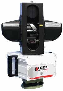
South Australia-based I-SiTE has developed the 4400LR, a laser scanning device equipped with a purpose-built panoramic digital camera which allows simultaneous acquisition of laser scan data and 360° high resolution color textures which can be automatically rendered over the scan. Instrument tilt is automatically corrected by a built-in digital level compensator. Setup, backsight coordinates and instrument height are stored with the scan data, so the scan is always located in the correct coordinate system. I-SiTE’s Handheld Controller (HHC) software provides a touchscreen interface for managing instrument control and scan configuration in the field. The HHC data recorder is a stylus-operated handheld tablet, connected to the ISiTE 4400LR via an Ethernet cable. Scans can be located automatically using the HHC, eliminating the need to postprocess data.
In a recent application note, I-SiTE reported that Chilean copper producer Codelco acquired a 4400LR Laser Imaging System for use at Andina, one of Codelco’s five mining divisions. Currently, Andina is mining Phase 2 of its Don Luis pit and Phase 2 of the Sur Sur pit, extracting about 80,000 tons of material per day. Mine development follows an aggressive design geometry, with a bench face angle of 80°, 10-m berm width, and single and double bench heights of 16 m and 32 m, respectively.
Andina acquired the laser scanning system for geotechnical control of the mine’s proposed design geometry; main applications include generation of program lines (toes and crests) as well as berm width, bench height and design angles. The I-SiTE system is also used for geotechnical control of waste dumps, calculation of mineral stocks, and stability control in wedge areas that are prone to movement. All of the data is processed using I-SiTE Studio software and then exported into VULCAN for mine planning. According to mine management, the system has allowed Andina to implement more stringent geotechnical controls to achieve the proposed mine design.
Slope Safety Software
Geo-Slope International’s SLOPE/W is software
designed to compute the safety factor of earth and rock slopes. The program
allows users to analyze both simple and complex problems for a variety of slip
surface shapes, pore-water pressure conditions, soil properties, analysis methods
and loading conditions. SLOPE/W can use finite element computed stresses from
other Geo- Slope programs such as SIGMA/W or QUAKE/W to calculate a stability
factor by computing both total shear resistance and mobilized shear stress along
the entire slip surface. SLOPE/W then computes a local stability factor for
each slice.
Probabilistic analysis can be performed by using normal distribution functions to vary soil properties and loading conditions. Using a Monte Carlo approach, SLOPE/W computes the probability of failure in addition to the conventional factor of safety.
Once a stability problem is solved, SLOPE/W offers a number of tools for presentation of results. Users can view information about the critical slip surface, including the total sliding mass, a free body diagram and a force polygon showing the forces acting on each slice, and then contour the factors of safety, or show plots of computed parameters. Finally, a user can add text labels, axes and pictures and automatically generate a detailed report of all input data and results.
Research to Reduce Costs
Laser, radar and GPS monitoring systems are fairly
expensive to rent or own, and thus are most often used by larger mining companies.
Researchers have identified a need for a less expensive system which allows
for monitoring multiple points on the pit slope. For example, recent work at
the University of Missouri-Rolla has led to the development of an economical
optical system which is claimed to be an alternative to electronic distance
measuring (EDM) or GPS systems for monitoring slope stability and is less expensive
than those systems.
The UM-R project is called High- Resolution Target Movement Monitoring (HRTMM). As described in a paper3 presented at the Society for Mining, Metallurgy, and Exploration (SME) 2007 Annual Meeting, HRTMM uses triangulation technique to track position of an optical spot projection and then image processing to measure mine wall movements. The system, according to the authors, can be easily automated and poses no obstruction to mine traffic.
The basic setup comprises a digital camera and laser light, and uses triangulation to measure distance changes between the monitor and the object. In the basic system, the laser illuminates one small bright spot on a white surface opposite the laser. The spot is then photographed by a digital camera located in a known location with respect to the laser. The digital photograph is sent to a personal computer where the XY coordinates of the spot within the image are calculated by custom-written software.
The theoretical accuracy and range of HRTMM depend solely on the resolution
and focal length of the camera being used, and the remote capabilities of the
system are well suited to applications where monitoring is required in high-traffic,
inaccessible, or unstable and dangerous areas of a mine. The system has to date
only been tested under laboratory conditions, where it achieved promising results
but requires further evaluation in the field, according to the authors.
References
Rolling Towards Stability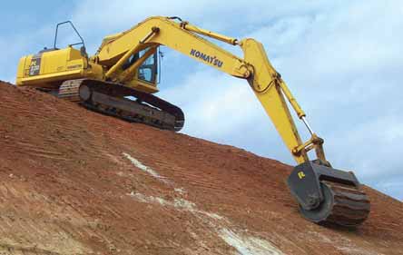 The Thompson Slope Packer attaches to excavators and can compact soil on slopes up to 10 times faster than a bulldozer or crawler tractor. According to Rockland, the Slope Packer method provides better operator safety when compared with packing soil using a dozer, and it compacts soils up to 10 times faster than conventional methods. It reduces fuel consumption, and eliminates undercarriage wear because the equipment no longer is required to “walk” the slope. The Slope Packer packs soil right up to objects and silt fences without causing damage. Because it frees tracked equipment for other uses, the Slope Packer offers better use of the equipment fleet. The drum is designed with ridges which indent the soil like bulldozer treads to control runoff and provide a bed for grass seed. The chains between the ridges remove buildup and allow the Slope Packer to be used on wet soil. The Slope Packer attachment is available in 4-ft., 6- ft. and 8-ft. widths for a variety of excavator sizes and can be used in conjunction with an excavator coupler if desired. |