SAG Mill Success—Start with the Basics
New products and techniques proliferate for maintaining and improving mill
performance,
but careful planning at installation may be the most effective tool of all
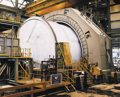 SAG mills are often flexible enough to accomplish the same
size reduction provided
SAG mills are often flexible enough to accomplish the same
size reduction provided
by two or three stages of crushing and screening, a
rod mill, and some or all of the
work of a ball mill.
• FFE Minerals Brazil was awarded a contract to supply a 26 x 16-ft, 6,500-hp
SAG mill—as well as a 21 x 32.5-ft, 9,600–hp ball mill—for CVRD’s
Paragominas bauxite mine in northern Brazil.
• Metso Minerals provided a 5,400-kW SAG mill along with technical services,
spare parts and supervisory services for erection and commissioning to Kunming
Iron and Steel Group Co. Ltd (KISCO) for its Dahongshan mine in Yunnan province,
China. Delivery was completed in the second quarter of 2006. Metso Minerals more
recently announced that it will supply grinding and flotation equipment to the
Gaisky copper mine of Ural Mining and Metallurgical Co. The order, valued at more
than €20 million, will be completed by the end of 2007 and comprises two
5,000 kW SAG mills, two 4,100-kW ball mills and 17 RCS (Reactor Cell System) flotation
cells, complemented by installation and commissioning support services.
• Wedgetail Exploration purchased a SAG mill from Thyssen Krupp Engineering
Polysius Division for installation at its Nullagine gold project in Western Australia.
The mill, which measures 6.1 m in diameter by 7 m long, is powered by a 3,500-kW
drive.
• Outokumpu Technology was selected to provide a 32-ft-diameter, 20-ft-long
SAG mill with 12,000 kW of installed power to First Quantum Minerals’ Frontier
project in the Democratic Republic of Congo. The trunnion-supported mill features
variable speed capability, allowing greater production flexibility and the ability
to cope efficiently with large ore variations. The Frontier mill is notable because
it highlights an approach toward over-coming what may be SAG technology’s
major challenge—load stabilization and control. A credible argument can
be made that the flexibility offered by SAG mills may also be their greatest weakness:
A mill that is touted to be capable of grinding anything that is fed to it, might
therefore be fed a mix of everything—ranging from vastly different chunk
sizes to variable
rock hardness. Feed variations such as this, as well as over or underloading a
mill, can result in less-than-optimum performance and make it difficult to achieve
satisfactory mill control. In fact, at least in part because of the attention
that must be given to the care and feeding of SAG mills, producers have begun
to look increasingly favorably at highpressure grinding rolls as a viable option
for grinding circuit design, either in combination with SAG mills or as a replacement,
particularly when dealing with lowgrade, abrasive ore. There are a number of laboratory
and software tools that can provide both preand post-installation solutions to
SAG mill power and feed problems. As an example, Dawson Metallurgical Laboratories,
based in Salt Lake City, Utah, USA, in association with the SAG Design Consulting
Group, offers SAGDESIGN test work and consulting. The SAGDESIGN test is performed
with a specially designed laboratory SAG mill and uses 7- to 9-kg (depending on
ore specific gravity) of –38 mm ore. The SAG product is then used as feed
to a Bond ball mill work index test. The results can be used to determine or confirm
SAG (or AG) and ball mill energy requirements. Other engineering and laboratory
firms offer similar services.
Variable Drive = Mill Efficiency
According to Outokumpu Technology, the advanced technology utilized in the Frontier
mill’s Hyper SER Drive ensures that the mill can operate efficiently both
above and below the synchronous speed of the motor, thus allowing better management
of variable feed rate and feed competency. The design also is claimed to facilitate
optimized handling of any short- or long-term variations in ore. Variable speed
offers optimized trajectory for the charge during mill operation, minimizing unnecessary
wear of the mill lining, according to Oskar Gustavson, Outokumpu Technology’s
global technology manager for grinding. “The beauty of this customized system
is that it is designed for optimal operation and can cope with pretty much anything.
This is critical, especially at remote sites which can be prey to challenging
situations such as voltage variations and thus unavoidable downtime. The Hyper
SER Drive can transfer to fixed speed mode during under-voltages, then transfer
back to variable speed when the supply voltage stabilizes, ensuring no costly
mill stops occur.” SAG mill breakdowns are costly events for producers.
As an example, early in 2006, Cia. Minera Doña Ines de Collahuasi had to
make temporary repairs on the drive on the largest and newest of its three SAG
mills at the Collahuasi copper mine in northern Chile, and then in mid-January
2007, finally began full replacement of the motor stator on the 21-MW gearless
drive for the 40-ft-diameter mill. The company expected the mill to be out of
action for approximately 65 days, representing about 30,000 mt of lost output.
The need to monitor and control these mills has led to the growth of a significant
sub-sector in mineral processing technology and product development.
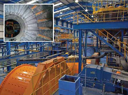 Metso Minerals helped Anglo Americans Lisheen mine improve
mill uptime by developing
Metso Minerals helped Anglo Americans Lisheen mine improve
mill uptime by developing
SAG mill linings that can be replaced without halting
production.
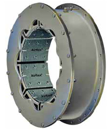 The Airflex 76VC drum-style clutch was designed to
handle the largest grinding mills currently available.
Focusing on Installation
With all the tools available for optimizing SAG mill performance, it might be
possible to overlook what could be the most important element of all in achieving
successful long-term performance: a careful, accurate and well-planned installation
sequence. The trend toward installation of large, gearless drive mills amplifies
the importance of this operation. At SAG 2001, Doug Farnell and Stephen Thompson,
both principals in Farnell-Thompson Applied Technologies, Montreal, Canada, presented
a paper titled Coordination of Mill, Motor and Plant Engineering for Large Gearless
Mill Projects. In their words, “The successful execution of a gearless drive
mill project requires that the mill vendor, motor vendor and plant engineer coordinate
their design efforts to a much greater degree than has been the case for most
traditional grinding mill projects. This coordination is critical to the design
of the three major elements of the system—the mill, the motor and the foundation—so
as to end up with a system that can be assembled, commissioned, and operated with
as few surprises as possible.” The authors divide the necessary tasks into
three main categories— basic design, operating and control logic design,
and installation coordination— and focus mainly on basic design elements
such as coordination of interfacing geometry/layout; structural design/analysis
of mill, motor and foundation; static and dynamic stability analysis of the overall
system; and coordination of services such as water, oil, air and power. Although
they recommend against assigning technical responsibility for overall design of
the motor, mill and foundation to any one specific entity, they do offer specific
guidelines for improving the technical coordination required to achieve a successful
installation. These include:
• Joint review by mill and motor supplier of foundation requirements, maintenance
access and clearances, and installation planning prior to submission to the project
engineer;
• Early exchange of data between mill and motor suppliers so that foundation
drawings from both reflect the same geometry;
• Improving the timeliness of the system studies such that there is the
opportunity to make any necessary design changes prior to fabrication;
• “Closing the loop” involving the mill vendor, motor vendor,
plant engineer, and owner on control logic implementation through joint review
of the final PLC logic; and
• Improved planning of the installation sequence, particularly in the area
of motor alignment vs. bearing adjustment so as to avoid repeating any tasks.